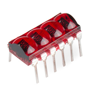
These little displays are no longer made unfortunately but I have a few knocking around and really love them. They are HP QDSP-6064 LED displays and where use in calculators around the 70's and into the early 80's. These displays really pretty and have wanted to do a project with them for long time.
So my idea is to try and do a watch, but better i want to get a modern MCU on there and have a debugging watch. something that is can use to send UART or I2C communications in a hurry.
There is one example of a bubble watch based on an the Texas Instruments MSP430, by solderbug.
I'd like something more capable than an MSP430 with an integrated RTC so i don't have to add more components than necessary. I'm looking at using on of the ST Microelectronics STM32F030C8. I packs a lots of power with a Cortex M0 32-Bit, with lots of peripherals. I comes i'm at around the £1.50 mark which is pretty good for amount of functionality. My only concern is its size in a 7x7 mm QPF package its going to take quite a lot of board space.
So i don't have much room to play with if this was going to be a single sided board, I also have to give room for a power supply. I want to get away form lithium-polymer cells (LiPo). If i was to use one then I have to look at how do I protect the battery from over discharging and how do i fit in a charge circuit while not costing the earth.
I have decided to go with a more humble pair of LR44 coin cells and using a boost converter to bring the voltage up. I think i will have to do some clever sleeping with the MCU to get the best out of this, but as the boost converter will run down to 1.2V input I sound get the most out of this format. Also going to have the battery voltage monitored by the MCU so it can issue a warning to change the battery, and as it is two cells in parallel it will be possible to change 1 cell at a time.
The MCU has a an RTC that can be used to wake up from standby mode. I fact there is no reason that when the display is bing looked at that the device has to be in any run mode at all.
This means the device and display could be drawing less than 10uA. :) (I'm this mode the device could run up to 11,000h hours).
So far at writing this I have the base power board routed and ready to go.
I unfortunately I am only just finished with routing the base/power board. I'm pretty happy with it, the LR44 cell holders are taking the majority of the board area but I have managed to find a little room for the boost converter.
My problems are to do with the display board. The number of through hole pins are making it difficult to put the board into a format that I'm happy with.
I was hoping i could somehow fit the MCU directly under the display, and as yet have not room for any IO breakout to allow add on modules.
I think my approach is to put SMT landings for the bubble displays and modify some DIP 12 sockets to be able to solder them onto the pads. I thank i'm going to take the same approach with the crystal and SWD header.
After a very quick search it seems SMT DIP sockets are freely available.
This is how far the project is a the writing of this blog I'm going to push ahead to try and complete it had hope that I can not fall too far behind with boards to follow.
I think my problem is this was quiet a complex project to try and complete in a week. and with this design change its set myself back a little. What this project is teaching me is sometime a redesign is what is needed and I have to just get on with it.
I hope to follow up soon with this design finished. Please let me know what you think, any comments are always welcome thank you to everyone who has given me feedback.


No comments:
Post a Comment