CHUSBIE552

Showing posts with label coding. Show all posts

Tuesday, 28 April 2020

The CH552 MCU

There is a collection of super low cost very capable MCU's on the market but I find myself fascinated with a manufacturer based In china called Jiangsu Heng Qin Ltd. (WCH)

WCH offers a range of hardware including the CH340 USB to UART converter IC the CH438 which is a parallel interface to 8 UART ports and an extensive range of 8 and 32 bit MCU's.


The one I want to look at currently is the CH552 MCU this chip is an 8 bit MCU based on the 8051 instruction set with an E8051 core but the most interesting point is that it has an extensive peripheral set including a USB controller.
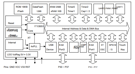


These are the onboard peripherals
  • Built-in 16KB Code Flash, 1KB XRAM, 256B iRAM, 128B DataFlash, support byte read and write;
  • Built-in BootLoader, support USB and UART ISP, provide ISP download library;
  • Built-in USB controller and USB transceiver, support USB-Device mode, support USB type-C master and slave detection, support USB 2.0 full speed 12Mbps or low speed 1.5Mbps. Support up to 64 bytes of data packets, built-in FIFO, support DMA;
  • 3 timer / counter, support 2-channel capture and 2 PWM;
  • Provide two full-duplex UART, all support high baud rate communication, UART0 is a standard MCS51 serial port;
  • Provides SPI communication interface, built-in FIFO, support Master / Slave mode;
  • Provides 4-channel 8-bit A / D converters;
  • Supports 6-channel capacitance detection;
  • Supports four reset signal sources, built-in power-on reset, support software and watchdog time-out reset, selectable pin external reset;
  • Built-in 24MHz clock source and PLL;
  • Built-in unique ID number;
  • Package: TSSOP-20, SOP-16, MSOP-10.
There is one downside to how the CH552 operates the 'Code Flash' as they call it is only writable about 200 times. This section of the flash is read only once your program is uploaded. To account for this there is a section of the flash memory called 'Data Flash' this is able to be written over 1 million times which makes it great for storing variables that you wish to keep after the power goes off.


There are many other little surprises as you dig into this component once you start looking into the clock selection register you find out that this little MCU is quite capable of running up to 32Mhz from the internal oscillator.
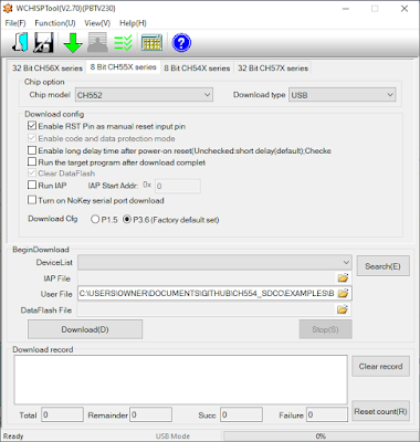
The device also has a built-in USB and UART bootloader which can be accessed by pulling P3.6 of P1.5 High when the device resets (depending on your configuration).

This chip comes in a variety of packages with different numbers of pins exposed. These include a SOIC16 package the CH552G, a  tiny MSOP10 package the CH552E, and a TSSOP20 package which has all the available IO and functions exposed the CH552T.

  

Software


There is a header file and examples available from WCH which help to get started including examples of how the USB device works. I would like to in time make this far more user friendly and much more generic.
There are a couple of software stacks fro the device:
https://github.com/HonghongLu/CH554 (for C51 in keil)
https://github.com/Blinkinlabs/ch554_sdcc (for SDCC )

As well as the Official ISP tool there is also an open source programming tool:
https://github.com/rgwan/librech551

The Store

I personally have a lot of love for this little USB hero and want to give it the exposure and credit it deserves. So to that fact, I have decided to stock it on my Tindie Store Rabid's Electronics Emporium.

I also have a Development board range on the horizon called CHUSBIE the I hope that you all grow to like this chip range as much as I do and I will do my best to make it available in many forms and a reasonable cost.
The overlaid packages look a little odd this is so the same PCB can be used for either the CH552T or G. I will keep you up to date on how that goes.

Monday, 15 June 2015

Simulating Keyboard Input in Python (Linux)

This is a big question that has very little good answers too it as I found out. Sorry if this is a little dry but this need to be shared.

NOTE: This is orientated towards Linux Python 2.6, the Windows Python solution is different.

How to I get Python to simulate keyboard key presses and releases?  For me this came up while trying to make a custom capacitive touch  controller with a on a Raspberry Pi for use with MAME or Minecraft Pi edition.

For this we going to use a Python Module called Uinput. This module can simulate keyboard, mouse or custom device. It can also migrate happily between programs in the desktop environment as well as the command line.

All of the following need to be completed on the command prompt or in a terminal window so if you are on the desktop go ahead and open your terminal program.


Prerequisites

There are a couple of extra development libraries that need  to be installed, before installing the python module otherwise Uinput will refuse to compile and install.

First of all it is always worthwhile making sure your apt repositories are up to date it is a good rule to do this before installing any new software, so to do this you need to
sudo apt-get update 
Then the development libraries that you need to install are libxtst-dev

sudo apt-get install libxtst-dev


Installing the module


Make sure that you have the python pip installer installed this will make it easier to build an install on your Linux system.
sudo apt-get install  python-pip
Then to install the module using the python pip installer.

sudo pip install python-uinput
If all the prerequisites are satisfied this will download compile and install the python module. :)

The module requires Uinput kernel module to be running this can easily be done with
sudo modprobe uinput
This will load the module this time round. I you want it to load every time you reboot your system then it will need to be added to the /etc/modules file. To edit the file from your command line.

sudo nano /etc/modules
Add an extra time to the line to the file with.
uinput
Then.
Ctrl + x
This will save and exit just hit  Y to confirm overwriting the file.


Using the module


So now that is all complete its only a case of writing some code.
import uinput
device =  uinput.Device((uinput.KEY_W,uinput.KEY_S))
import time
while 1:
        device.emit(uinput.KEY_W,1)
        time.sleep(0.5)
        device.emit(uinput.KEY_W,0)
        time.sleep(0.5)

This is a  little sketch to setup a two button device I'm just using this as an example but any device can be made with any number of keys so lets have a look at the code.

Lets have a look at what the code is doing.
import uinput 
This imports the required module into your python sketch.
 device =  uinput.Device((uinput.KEY_W,uinput.KEY_S))
This line creates a uinput device with two keys W and S all the letter keys emit as there lower case version unless it is modified with a shift.

import time
imports the time module for handling delays
while 1:
Repeat forever
        device.emit(uinput.KEY_W,1)
Keydown w key
        time.sleep(0.5)
wait 0.5 seconds
        device.emit(uinput.KEY_W,0)
Keyup w key
        time.sleep(0.5)
  
 This module could be used for making custom combos for games in MAME like street fighter or just allow automated control of some command line tasks. I am currently using it to make a custom game controller on with a Raspberry Pi's  GPIO connection.

Hope this helps out a few people as I found it tricky to get up and running in the first place hopefully I have covered that so people don't have the same difficulty.


Sunday, 14 June 2015

Fun with the Silicon Labs BIOMETRIC-EXP-EVB development board

This week I've been having a good look at the the BOIMETRIC-EXP-EVB dev board from Silicon Labs a Fab-less chip manufacturer based in Austin Texas.

The board is designed as an expansion board for their EMF32 Wonder GEKO development system. The board contains a SI1146 Ambient, IR , UV and 2D Gesture sensor, SI7013 Temperature and humidity and a TS3310 step up DC to DC coveter. The dev board also contains a Microchip 24AA024 eeprom that I believe it communicates with other Silicon Labs contains specific info about the board. It also has a green and red LED for good measure. This development board is around $29.00 at the moment so if you fancy toying with a selection of sensors then I recommend it.  

 This week I've been specificity trying out the  SI1146. This chip has the ability to  measure ambient light level, Infra red level and  measure UV index which is a standardised measurement of UV light level normally used in calculating sun burn time. The chip is also can sense 2D gestures using 2 external infra red LEDs its internal LED constant current driver and taking independent reading of refection from each of the LEDs with can then be used to calculate distance on 2 axis (distance from chip and north/south or east/west depending on the LED location)

Wiring up 

Just to note the development board is runs both power and logic at 3v3 so if your are using a 5v platform like and Arduino Uno you will require a I2C compatible logic level shifter for that data lines or there is a risk of damaging the dev board.

All the devices on the board communicates with a two wire serial protocol called I2C. This is a bus based protocol that requires devices on the bus to have individual 7 bit addresses. To use these I2C devices SDA ( serial data ), SCL (serial  clock ) and GND ( ground ) need to be connected.

 There is a little bit of a got-ya with wiring up this board  in the datasheet states that the the Si1146 SDA is connected to pin 16 and SCL is connected to pin 17 this is true for the JP3 header this is the one on the left side of the board, but on the right side the JP4 header it is connected to pin 15.  The INT pin is used for interrupt driven reading of the sensor when it when a sensors readings are ready this pin will change.

For my tests I'm using a Raspberry Pi B+  and coding in python using the SMBus module which runs the Raspberry Pi's I2C bus.

The pin numbers start at the bottom or south of the board and go across the header starting from the bottom row hopefully this picture makes more sense.


so hook up:
Raspi                                              Biometeric board
Pin 1                     3.3v                    Pin 2
Pin 3                     SDA                   Pin 16  
          Pin 5                     SCL                    Pin 17 on JP3 or Pin 15 on JP4
Pin 6                     GND                   Pin 1

Software 

I have spent a few hours getting this to run in Python and at this moment still working on the code to make it into a python module for the Si114x range possibly for a future development. My work so far is available on github Here.

The moment it is just a single program that runs the Si1146 and outputs its data on screen. 

So just type:

git clone https://github.com/rabid-inventor/SI1146-software.git
Then
cd SI1146-software/RaspberryPi/Python/
and to run the python script
sudo python si1146.py

This will output UV index , Proximity sensor and visible light level.

currently having a lot of fun with this sensor and will keep updating especially when I get as far as using the sensor to measure pulse and 2D gestures. At a later stage I will be revisiting the Si7013 temperature humidity sensor an see if I can finally get it running with a Raspberry Pi.