CHUSBIE552

Tuesday, 10 March 2020

Designing and building a computer that's 40 year out of date (part1)

achI have seems to have taken on several personal projects this year. I have been wanting to learn about FPGA's and have been fascinated by the prospect of running a whole processing core inside a programmable silicon matrix. But to get to that point I seem to be taking a long convoluted route around it. Let me try to explain.

I want to design a board based around the Gowin littlebee FPGA I think it is going to be the GW1NSE-C2 which has an embedded ARM Cortex M4 processing core. So deep into the datasheet jungle, I go and start designing a board. After much reading, I realize that is going to need a JTAG programmer of some type. so after much research, I find a project for as low-cost JTAG programmer based on an MCU from WCH who also makes a low-cost USB->UART chip which I have looked at in the past. So this sparks off another PCB project, SimpleJTAG.

Somewhere in the middle of this, I run into the low-cost RISC-V MCU's from Gigadevice and with a fascination in RISC-V and a new JTAG programmer on the horizon I start investigating how to source these. Is everyone still with me :)?

Back to the FPGA project, I started with so now I have a JTAG programmer on the horizon and maybe another MCU board not even going to mention the Tindie shop (yes another thing I'm working on). I dive into Gowin's EDA tool for configuring their chips. After much poking around in the dark I find out how to activate the ARM core and become totally lost as I am made aware of my huge gaps in my knowledge when it comes to SOC architecture. Though there is an ARM core on this chip all the flash, ram and peripherals need to be configured inside the FPGA fabric and with the choice of either Verilog or VHDL to program this in I discovered in need a better understanding of computing architecture.

This is where I run into a video series from 'The 8-Bit Guy' on the history of commodore computers with some really nice detail on the system architecture. So to solve the gaps in my knowledge its time to design and build an 8-bit computer from the 80's.

Why make something so outdated?

The early home computers have a very straightforward system architecture ROM, RAM, and peripherals. I can understand the system as a whole and can break it down into constituent parts. Modern hardware has so much integrated that there is no chance of having a complete understanding. Also, there is a big nostalgia factor I can remember going to my neighbors and loading games into is ZX spectrum and using my brothers ZX+3 while he was out and writing early programs in basic.   

Of course, the first task ahead it to try and pick a processor for this design (MPU) I need something simple which old acts a processing unit if it contained its own ROM or RAM then I would defeat the process of the learning system architecture. I looked at both the Zilog Z80 and the MOS6502 as possible options, then I ran into ubiquitous almost forgotten Motorola MC6800 which proceeded the other two by a couple of years.

The first look at the datasheet of the MC6800 I was slightly put off with the clocking requirements. It required two clock signals.
The signals are not quite inverse to each other and would require additional hardware to generate. There is a single chip clock generator also made by Motorola the MC6875 but after a quick search it seems to be quite rare and at over $10 e a bit rich for me.

But then I found a later version of the same processor the MC6809 which had some extra features and had the clock generator internal to the IC and only requires an external xtal to run it.
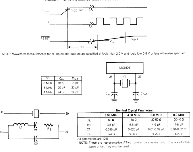
This was the MPU I was going to use. I found a similar project which gave me some initial guidance. https://sites.google.com/site/gogleoops/mc6809-min-board Which is giving me a lot of direction when it comes to working out address select logic and how bus timing and R/W.

So the first board its basic structure looks like this.

I found an online assembler and debugger which seems pretty good

https://www.asm80.com/
The compiler has options to step through the program and see how it operates its really shown me the specifics when it comes to what the Reset Vector is (I thought it had the first instruction but in fact, it is a memory address which is written to the program counter where the first instruction is located). Also how the stack pointer works with subroutines and how easy it is to cause a stack overflow :).

I have routed the first revision of this board I think it looks pretty good.
I decided to go for a mix of surface mount and through-hole parts as this project is just for me o don't see myself making huge numbers of them. 


Updates on this project can be found on Hackaday.io
https://hackaday.io/project/170307-basic-mc6800-interface-board


Tuesday, 26 February 2019

BAW!! A very late new years update

Hi folks

Sorry for being so quiet this year so far I have had a massive PCB project I have been working on with someone and has consumed the time I would normally devote to Board a Week.

Unfortunately I can't say too much about it at this moment the project involved 4 different boards one of them being a 6 layer monster, all with KiCAD WOOO! go open source EDA.

Incidentally I have been working on other boards for Board a Week. M0GO I have completed and the Gerbers are in the GIT hub repo.

I should have a blog post coming for that very soon. Also the bubble watch original for week 4 is now complete.

Can't wait to make that one ;) I'll have a little write up of the details later. 

On top of everything have managed to assemble a couple of these boards. The great thing is the seem to be working well.


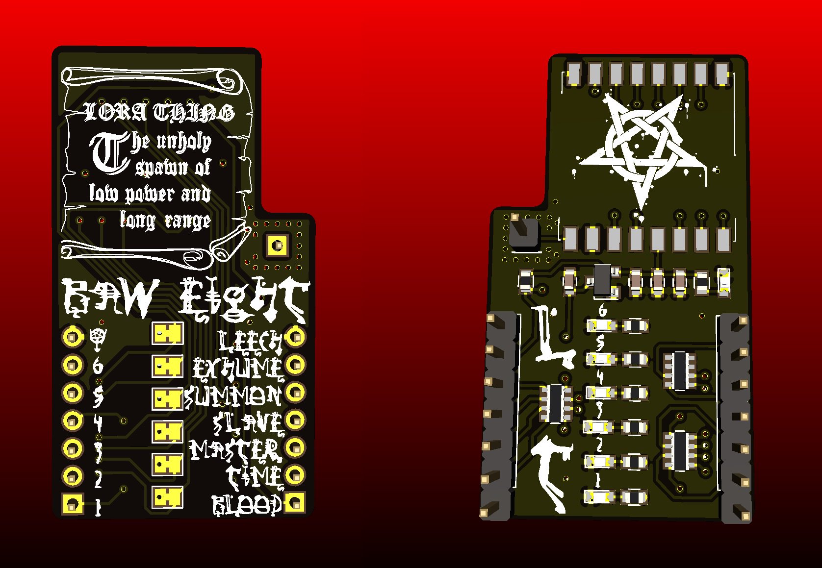
Both Lora Thing and Give Me Power arrived safe and sound from JLC PCB The have done quiet a nice job of them. 


Give me power works very well using it actively  😊


I also had the opportunity to design a breakout board for work for the PAM9081 3W  stereo amplifier super quick job but my boss seem happy as it worked straight out.

I realize this is a super quick rundown of what has been happening over the last few months I have a couple of BAW projects in the pipe currently doing an HDMI multiplexer called HDMy should be fun and going to do a stand alone LORA sensor node.

Hope you like the update remember all these projects are in GIT hub http://github.com/rabid-inventor/board-a-week.git

More Posts are coming soon......


Thursday, 13 December 2018

BAW: Update

FIRST OF ALL


Hi all,

I feel its about time I gave everyone who reads this blog a bit of an update on what is happening with board a week.

I think the first thing i have to really say is that I am still designing boards on a semi regular basis I still have much to learn and want to continue making boards.

I think one thing I i have had to except is that currently I am not able to design a board a week, and I is not due to drive to do it. I have other responsibilities that need to be met first whether that is to my family, my work or just to have a little time for myself. The hard thing is to admit is I can't do it all even though I try.

I think the other think I have to keep in mind is not to be too hard on myself about all of this, I think just making little strides towards getting something completed is as good as going heavily from start to finish and being frustrated when  I can't achieve this goal. I think I discovered that in week 4 trying to complete the bubble watch in one straight run proved not to work. that one i will come back to soon. I the meantime i have learnt far more about the STM32 platform which will allow me to go back and complete it. 

WHERE I AM NOW


As BAW is at the moment I'm putting the finishing touches to Week 9 M0GO a USB Device Dev Board. I think after that it will be a revisit to Bubble Watch.

On the subject of having these boards made, I have just send of the Geber files for both Week 8 LoRA Thing and Week 7 GiveMePower hopefully will have those before Christmas. I think I have missed the boat for doing a board for Christmas but defiantly have something in mind for valentines.


AND FINALLY 

I would like to take this moment to say a big thank you to everybody that has encouraged me to do this either with friendly words or likes and retweets. I have I continue to be of some interest and hope that others can learn from my mistakes.

Please continue you support and all updates are on my Git Repo https://github.com/rabid-inventor/board-a-week

Friday, 12 October 2018

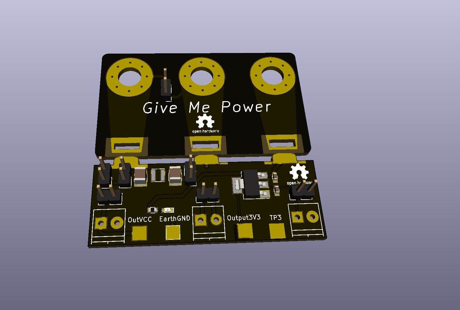
BAW!! #7 Give Me Power

Sometimes it occurs that the piece of equipment that you are using could be better or have better features maybe adapted to suit your needs better.


This is my bench supply i'm currently using, it work fine on the fact that it supplies power to whatever om working on but it has a few quirks which quite frankly drive me nuts on a daily basis.

I can't set the output voltage without turning the device on, which means if you have a project wired into the terminals you have to unplug it turn the supply on set the output voltage then turn the supply of wire your project back in then you can power it at the write voltage.

The other thing I would like to have is a dedicated 3.3V supply at the moment my solution to that is using an half broken Raspberry Pi powered from a USB port as my 3.3V supply which to be honest is no the best solution. 

The easiest solution to all my problems would be to invent in a good bench power supply. But that would leave me out of pocket and there would end up being a power supply sitting on the shelf unused. 

So lets look at designing an add on board to make it more useful. 

The functions I want to add are:
  • The ability to set the voltage without having to disconnect from the supply.
  • A dedicated 3.3V supply, preferably a linear regulator of up to 1A current supplying.
  • A select-able low pass filter for low noise applications.    
  • An auxiliary channel for current measurement.
  • Hooks for attaching oscilloscope probes. 

The schematic is pretty straight forward not much in the way of active components just lots of connections.


I'm still working with KiCAD finding easier and easier to use each time I complete a board I seem to find a new feature. I this case i was coming to the end of routing the board and there seemed to be a connection missing between EarthGND terminal and a a pin header which is used to link EarthGND to supply ground if necessary. I had managed to label the pin connector as EarthGround instead of EarthGND I was on the final trace and wanted to finish routing the board. 

This is when is discovered that it is possible to change the net of the pad in the layout editor, bonus!!! It mean ti could finish the routing straight away without having to go back to the schematic and change it reexport the net list then re-import it in the board editor.

This is not the 'proper' way to do things because it them means the schematic still has the error and would have to be updated at a later date. But in a pinch it seemed to work. 


Something I have always done is to print a paper version of most boards I design and this one was no exception. As I was designing to fit to another device it was important I hadn't made a mistake.   


To my relief it appears to fit well. So it means there a high possibility the finished board will fit nicely also. 


All done and routed ready for the next one.

Saturday, 15 September 2018

BAW!! #6 Blink AN Led competition: BlinkIR

Ok time to really go for it, I discovered that Mouser an electronic component distributor and Macrofab an electronics manufacture with a down to earth approach, are running a competition to design a board to blink a LED, called Blink An LED.

I'll try to post as much of the process of concept and design as I go, the full posts, files and documentation is available at  HackADay.io also this project will have a separate repository for the time being until iIadd the finished version to the main board a week repo.

I finally have the boards and making them up slightly outside of the competition deadline, finally made some up.


The biggest relief was getting them to program. 


And then them blinking. 
I will pull this project into the main Board a week repo as soon as I can. In the meantime the project can be found here:

And the full write up here:


Wednesday, 29 August 2018

BAW!! #5 Lets try a new IC (Part 2 Rushing to finish)

Sometimes I find its less about pretty and more about speed. As mentioned in the previous post the BMA400 is a brand new device not even available but having a board ready to receive it can be a big advantage of bring a product to market.


Certainly not the prettiest board I have designed and i was have some difficultly get the Silkscreen Graphics how I wanted it. 

But just over two days it was finished. I normally take the time to sit with a board just to make sure i haven't made a mistake. But there is one great big one on the silk screen.

The design files can be found at:

Feel free to download, clone and remix how you want :) I'd like to know what you get up too.


Sunday, 26 August 2018

#BAW!! Weeks 5 Lets try a new IC (Part 1 finding the data)

Still running quite far behind the Bubble watch from week 4 is still an in progress project I'll keep everyone updated as I get more work done on it.

Sometimes a change is as good as a rest so its now time to try a new approach. What about a new IC at this point i'm going to pick something new from Mousers website ( mouser is a component disributer I like their new product search )

First item i have found on the page is a new accelerometer from Bosch Sensortech according to the page it was shown of at the most recent CES and receiving awards for innovation. This is many due to its ultra low operating of around 8uA (super low) thats about 20 time lower than their other Accelerometers at around 150uA operating current.

Its always funny with brand new IC products the offer very little information to even Bosch-Sensortec's own page has very limited technical detail. 

These are the only two documents available at this moment in time:  

A nice give away is the schematic on the shuttle board document which shows how the device is decoupled, and give an idea of how its supposed to be connected as typical application.


Another thing to do is look at the previous generation of the device. At the moment Bosch manufacture the BMA280 which is the previous accelerometer device from them.

I took a look at the datasheets of other Bosch devices and discovered the register map for the device are for the most part identical. This will be a good reference from bringing up this device. 

Time to start making a symbol for the part. I have the Pinout.


I draw it into the KiCAD symbol editor I also find it useful to make sure the do not connect pins are drawn in they can be useful for reference later and making sure the footprint is correct. KiCAD can suggest the correct footprint based on the number of pins so it useful to have everything in front of you.

Time to work on a footprint for the part. I am using the datasheet for the BMA456 being one of the more recent accelerometers i can use the application notes to help draw in what I need for this board.    

schematic is now done leaving enough landings for pull up resistors and jumper links to select the different communication modes. The BMA400 supports both I2C and SPI protocols and there is also an I2C address select.