I got interested in this watching Gadgetiod solder up the realising that it wasn't just another FTDI FT232R (being honest no happy with them after the hole bricking your device scandal, long story) or a Prolific PL-2303. It was using something unexpected Microchip MCP2221.
This little chip is not only a basic USB to UART bridge it can also bridge to GPIO, I2C and a tonne of other functionality. This really peaked my interest but that will be for a later blog post. This post i'm looking the assembly and what comes in the kit.
The Debug Clip clip comes in kit form requiring soldering together don't be too put off by this as all the joints are well spaced and it has plenty of guidance on the PCB's silkscreen.

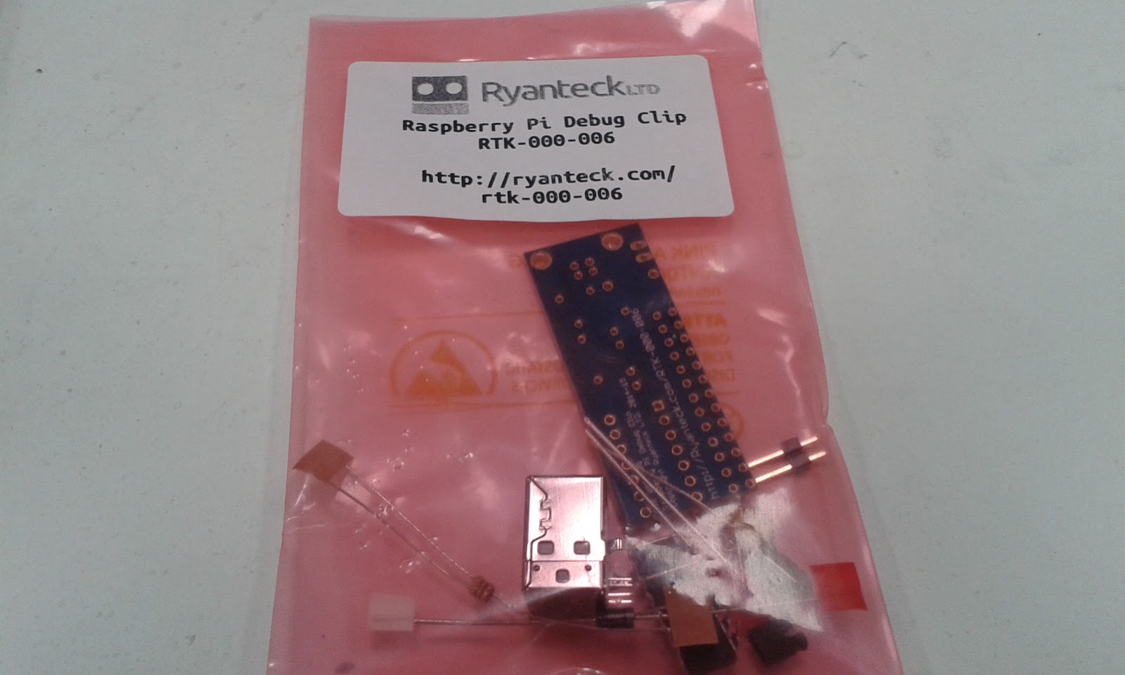
In the kit is:
- PCB
- A USB Type B socket
- A two pin header with jumper
- A green and a red LED
- A diode
- Two Resistors of the same value
- A fuse
- And the MCP2221 IC itself
One thing to note there was ESD foam protection on the legs of the IC. The foam would offer some electrical protection but the main reason would be to prevent the legs from being damaged in shipping.

The kit feels well thought through, the silkscreen on the PCB makes assembly even easier. There is a clear assembly guide provided by Ryan Tech but the Silk was so clear I didn't even need to look at it.
Assembling
There are only a few things to make sure the orientation is correct the IC, the diode and the two LEDs.


I started assembling mine with the diode and resistors the have the lowest height to the board and folded the legs outwards before soldering. Then solder and trim with some side cutters.

The IC itself was next in height order it always worth making sure that the notch on the IC matches the pattern on the silkscreen.

Next I decided the the USB socket would be the best as it would create a flat surface to rest on this help with supporting the header when soldering that in, making sure to solder one contact on the header first and then reheat the join and push the part flush with the PCB (Mind you fingers it could get hot)
Then it was onto the LEDs I chose the green one for RX and the red for TX. The positions are well marked with a little + for the positive side, which is the longer of the two LED leads.

The last component I assembled was the fuse then all was done for the moment.

All ready to plug into your Raspberry Pi and PC's USB port.
Installing drivers
The Debug Clip's driver are not available in windows update at the moment but can be easily downloaded from the Microchip MCP2221 Product page.


Then the device should appear in your device manager. This would be a really good point to take note of which COM port the Clip appears on. (In my case it is assigned to COM10).
Once you have Putty running click on the Serial radio button and enter your COM number that you noted earlier and set the speed to 115200.


Then you can just use it as though you are on the Raspberry Pi's command line.
I like the Debug Clip and it is nice to have the blinking green and red LEDs as the data is going back and fourth. It makes a good alternative to the FTDI or Prolific based boards that are out there. the assembly we very straight forward with no real issues. I give it 4 sparks, 3 for the device and and bonus for hack-ability.


If the device is working correctly it will appear in your device manager as other devices -> MCP2221 USB-I2C/UART Combo. Please note that the Clip will not work unless placed on a the Raspberry Pi's GPIO header, as it uses the Pi's 3.3v regulator to make sure the UART output is 3.3v so it doesn't damage the Pi. Also make sure that the Pi is on.

So now go ahead and download the appropriate driver for you. I'm running a Windows 8.1 laptop so mine is the Windows Driver & Installer.

Once downloaded open the archive and extract the files.
Navigate through the Driver Installation Tool and relevant 32 or 64 bit version and right click on the .inf file and select install from the menu. ( for me the installation tool didn't work )
Using the Debug Clip
You are going to need a remote terminal program if you don't have one already, I use Putty and would recommend it for most users. I can be downloaded form here.Once you have Putty running click on the Serial radio button and enter your COM number that you noted earlier and set the speed to 115200.

After clicking open a terminal window should appear and you will be asked to login with the normal user name a password.

I like the Debug Clip and it is nice to have the blinking green and red LEDs as the data is going back and fourth. It makes a good alternative to the FTDI or Prolific based boards that are out there. the assembly we very straight forward with no real issues. I give it 4 sparks, 3 for the device and and bonus for hack-ability.
Then next Post do will be about modding and hacking the Debug Clip.


