USB-C is more and more becoming a standard in the maker community for power supply and coms with peoples creations. But there is a catch to this although the USB A plug to USB C plug cable is freely available almost everywhere, the sockets can be a little more daunting. There are not only many to choose for including some with and without through-hole pin the pitch and spacing often means you have to spin a PCB to make them work. then there are concerns with soldering them effectively.
Who wants some PCB USB-Micro breakouts? I have like a billion, they're so much fun pic.twitter.com/xbk6nVj9JW
I started to wonder if this would be possible with a USB-C socket with one edge of the PCB inserting into the USB-C plug connector directly. I did a quick Google search and was very surprised that this seemed as though it hadn't been done before. 😏
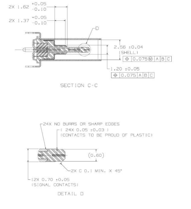
And there it was the "tongue" of the USB-C receptacle is 0.6mm wide wit the contacts proud of the Plastic or in my case PCB.
Wondered if 0.6mm PCB would break the bank in production costs so it was time to have a search around. My usual stop now for PCBs is JLCPCB. Is I went and had a quick look to see that it wouldn't cost the earth to at least experiment and see if this is viable.
Surprising enough that even with a lead-free finish it would only cost £6 including shipping, at least to do some experimenting.
Even if I ordered V-cut panels which would give me 90+ pieces they would cost less than £0.13 each.
It was slightly shocked at how the price jumped when I selected my usual black solder mask finish, with a large "Special Process Fee". That would certainly blow the budget feels like I'm ordering boards in 2013 again 😅. Looks as though I want to be able to sell these at a reasonable price then they will have to be green.
With my mind made up it was back to the USB-C spec sheet.
Time to fire up KiCAD and get on with creating the part.
It took a bit of drawing but here is. there is something that I found frustrating within KiCAD. this is I couldn't find a way to draw on the edge cut layer in the footprint editor. Not entirely sure if it is something I missed but decided to draw the board edge into the user drawing layer that I can copy over later.
At the end of the day, I just want to see if this is a workable design so decided that making a breakout is the best plan.
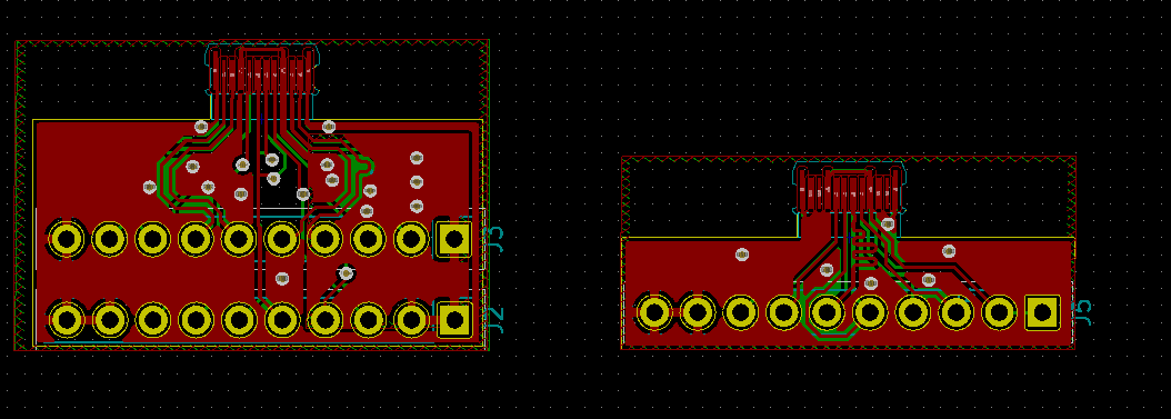
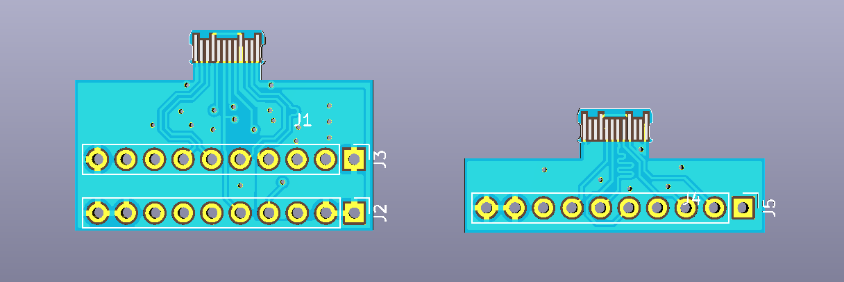
So far I have done two designs the one on the left has all 24 pins broken out for USB-SS and the right one is just for up to USB-HS. All the highspeed lined have their differential traces matched in length but the SS traced don't have the required supporting hardware, caps and filtering etc.
It was around this time i started to tell people what I was up to at which point I found there have been a few previous attempts at this type of connector.
Been there, done that, it is not worth it. The connection is super flaky, it wears off quickly and with a 3D printed case it's not even cheaper. pic.twitter.com/Qs3lwCRHlV
I'm not put off exploring this path however I still think this could be a viable option could do with some tweaks in the long run. The other reason for continuing this is I don't think this option has been completely explored of documented yet.
At this point, I'm making some final tweaks to this design and hopefully sending off for production next month.
If you are interested in exploring this concept yourself all my Kicad files are available on Github so feel free to use them as you desire.
For a few years I have been looking at different MCUs with USB capabilities in most cases there are not many sub $1 parts that fit the bill.
If you want something small and discreet that does a few USB functions there isn't much around, normally the barrier to entry on these types of MCUs 8 bit and 32 bit included is over the $2 mark. The issue start to become when costing the bill of materials $2 on the BOM becomes $8 by the time you get to retail price.
There are a few low cost MCUs out there like the range from STC or Nuvoton once you add a USB transceiver the cost seems to double.
I know it sees to be very focused cost but with companies form overseas being able to produce USB devices with the low retail price there must be some solution out there.
My over all goal is to demystify USB and develop a platform that gives developers confidence to develop USB devices without large overheads or in some cases complicated stacks that are beyond comprehension.
I have spoken about my admiration of the CH55x range from WCH that are a series of ultra low cost micro controllers with USB in some of the range is down in the $0.25 category in volume. Which is unbelievable a full capable MCU for the same as a discreet logic IC.
As well as the USB2.0 transceiver and the E8051 processing core itself they come with a resonable array of peripherals as well 2 x UART port, SPI , 4 channel 8 bit ADC and 10k to 64k flash space in the case of the CH559.
There are a few dev boards out there for the CH55x range mainly from electrodragon with their CH55x range of boards. They are a nice range but I feel they have a couple of points that I would love to see improved on.
This is why I decided to start the CHUSBIE range starting with the CHUSBIE552 based on the CH552T or CH552G a lower cost less IO version.
With the CHUSBIE552 I have added onboard functions that I think will be the most useful to a developer like:
onboard reset and bootloader buttons
RX and TX indicator LEDs
sensible pin-outs with pins and ports in order
optional landing for external XTAL crystal for precision timing applications
Power indicator LED
I would like to see a general adoption of the CH55x range chips in a similar way to the ESP8266 and ESP32 (notably neither of which have native USB which in my humble option would be a killer addition).
I want to work on the software stacks to make them more friendly for a start making sure the Chinese comments are translated to English for the examples especially the USB ones. My point is that USB doesn't need to be this mystical black box that can't be easily accessed by most hobbyists and makers.
So far in my research I found firmware for USB CDC device, USB HID device and USB JTAG device all of which i am trying out to incorporate into a master repository.
I have not been hiding the fact that I have love for the CH55x range of microcontrollers. So much so that I decided to stock several versions on the store. If you want to get hold of a few to experiment with check it out at Rabid's Electronics Emporium
I thought it's about time to write up a little tutorial on how to get up and running with this little unsung hero.
For this getting started tutorial I will be specifically looking at the CH552G but this tutorial will also apply for the CH551x, CH552x and CH554.
Installing the Toolchain
This is not the only way to set up this toolchain there are other compilers and toolchains available, this, however, was the most straightforward way I found to get up and running.
First off the best thing to do is to install the compiler for this tutorial. We are going to use SDCC (Small Device C Compiler) this compiler runs natively in most linux flavours but if you're developing on a windows machine like I am then it will be worth setting up WLS (Windows Linux Subsystem) and installing Ubuntu.
As I mentioned I didn't use this method but if you feel a little more comfortable using it instead of installing WSL and Ubuntu it's worth a shot.
Preparing the hardware
The MCU itself requires very little hardware to run in USB programming mode. Though a reasonable soldering skill is needed to solder the chip into a proto-board. There are many tutorials online on the best method to do this.
The above video is a very similar method to what I use. I am also considering stocking some already soldered on the store, as I will soon have the prototyping boards available.
Once you have your board soldered and pins attached the rest of the circuit can be made up, on a breadboard. For me, I found the easiest way to attach the USB signal was to Butcher an old USB cable and solder Dupont jumper wire onto the exposed ends.
This has been really handy while I have experimented with this MCU.
The rest of the supporting circuitry can be made up, on a breadboard all it requires is 2 x 100nF ceramic capacitors between 3v3 and GND and between VCC and GND as down below.
If the chip is new and fresh from the factory then from my experience it drops straight into bootloader mode no a widows PC it makes the always familiar USB device sound :).
Of course, if this doesn't happen then the MCU will need to be set into bootloader mode.
Putting the MCU into USB Bootloader mode
There are two possible bootloader pins ton the CH552 the default from the factory is on P3.6. To active the bootloader the pin must be pulled to 3V3 briefly after reset. This can, however, be very problematic as the same pin is shared with USB DP. So for my purposes, I like to set up the bootloader pin as the available alternative which is P1.5 there is a catch though this pin ins needed to be pulled to GND.
Writing Firmware to the MCU
First of all, you will need to download and install WCHISPTool this is the official and poorly translated to English tools from WCH themselves.
Oddly enough the English WCH site doesn't give you any of the download links to the tools of datasheets so you will have to go through the Chinese site.
once the software is installed and running it will look much like the above. You will need to select the '8-Bit CH55x series' tab and select the CH552 as you devise then all being well your device should appear in the device list below.
This tool gives you a few configuration options like:
Disabling the reset pin
Enabling slow reset
Erasing the data flash
Swapping the bootloader pin to P1.5
From my own experience swapping the bootloader pin is worth doing for me it helps getting it into bootloaders mode as P3.6 (the default pin) is shared with USB Data + which cam make things awkward. Where you have P1.5 tied to GND was very helpful for me as the MCU then automatically goes into USB bootloader mode every time it is reset or powered.
To test the function everything is well if you select the user firmware you would like to use I used blink which but this point should be in the toolchain examples.
\ch554_sdcc\examples\blink\blink.bin
This will need to be selected as your 'User file' the click on Download(D) all being well you will have some lovely green text in the download record below saying the process was successful.
All being well if you hook and LED and resistor between pin P1.7 and GND then you will have a lovely blinky LED.
Starting your own application
This is very simple from mine I copied one of the examples and I started to edit form and just use the make command to compile it.
After a bit of trail and error managed to make it run LPD8806 strips of LEDs.
Messy but works :D
What I would like to do now is to add a USB CDC driver so I am able to adjust the colours over USB.
I have a both the CH552G and CH552T which has more IO are listed on my Tindie store.
It work brilliantly with the Raspberry Pi but I would like to use it in some of my other projects and put it through its paces or at least the USB bridge IC the MCP2221 by Microchip.
The first thing I want to do is hit the data sheet and see what other functions the MCP2221 is capable of.
OK, Ryan Tech I have to admit this chip is really cool I hadn't noticed that it has an onboard ADC as well. This is all on top of the standard GPIO, UART and I2C capabilities.
Hack #1
Soldering a header into the the debug clip. This is mainly so I am able to use jumper wires to hook it up to other devices.
For me I find female socket most useful for the stuff I like to mess with. This just allows to make the connections mainly the first one being connecting the power so the debug clip can run without being attached to the raspberry pi.
Hack #2
Powering The debug clip without a raspberry pi. The Debug clip has a voltage fail safe mainly for the Raspberry Pi. The MCP2221 runs from the 3v3 voltage rail of the RasPi but this also means it will not run on its own.
This is fixed by using a a jumper wire between the 5v connection and the 3v3 .
WARNING: This will mean the debug will be running at 5v do not connect to the RasPi's or other 3v3 devices GPIO It could damage it. This is why I use the socket and jumper wire without soldering at the moment.
Hack #3
This is a bit of a dirty hack to get the 3v3 power onboard. I have a few AP1117 LDO 3v3 voltage regulators. I'm going to hack one onto the underside of the board this will give me a selectable 3.3volt supply.
A few flying decoupling caps as recommended in the application notes. A bit of jump leading on the to and all is well.
Now the UART is running at 3v3 again without a raspberry pi. and now running with a Ublox Neo-6M GPS module.
With some nice tangible data returning to putty. I'm doing this indoors so I don't have a GPS fix but the data connection work very well.
Further hacks
There will be more hack coming with the debug clip like changing its function and using the I2C interface, and this little device is sure to make an appearance as useful tool in future posts.
I was passed a Ryan Tech Debug Clip, a little board that allows you to connect to a Raspberry Pi via USB and the UART connections on it's GPIO this was due a good friend of mine Gadgetoid had 2 from backing the Kickstarter.
I got interested in this watching Gadgetiod solder up the realising that it wasn't just another FTDI FT232R (being honest no happy with them after the hole bricking your device scandal, long story) or a Prolific PL-2303. It was using something unexpected Microchip MCP2221.
This little chip is not only a basic USB to UART bridge it can also bridge to GPIO, I2C and a tonne of other functionality. This really peaked my interest but that will be for a later blog post. This post i'm looking the assembly and what comes in the kit.
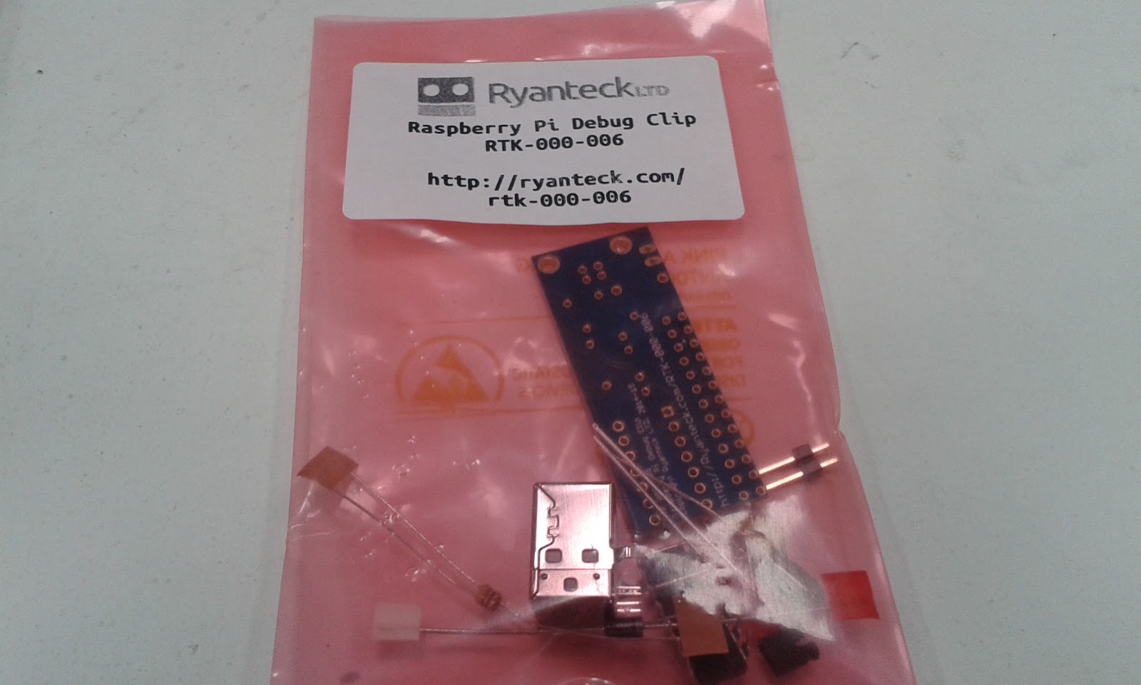
The Debug Clip clip comes in kit form requiring soldering together don't be too put off by this as all the joints are well spaced and it has plenty of guidance on the PCB's silkscreen.
In the kit is:
PCB
A USB Type B socket
A two pin header with jumper
A green and a red LED
A diode
Two Resistors of the same value
A fuse
And the MCP2221 IC itself
One thing to note there was ESD foam protection on the legs of the IC. The foam would offer some electrical protection but the main reason would be to prevent the legs from being damaged in shipping.
The kit feels well thought through, the silkscreen on the PCB makes assembly even easier. There is a clear assembly guide provided by Ryan Tech but the Silk was so clear I didn't even need to look at it.
Assembling
There are only a few things to make sure the orientation is correct the IC, the diode and the two LEDs.
I started assembling mine with the diode and resistors the have the lowest height to the board and folded the legs outwards before soldering. Then solder and trim with some side cutters.
The IC itself was next in height order it always worth making sure that the notch on the IC matches the pattern on the silkscreen.
Next I decided the the USB socket would be the best as it would create a flat surface to rest on this help with supporting the header when soldering that in, making sure to solder one contact on the header first and then reheat the join and push the part flush with the PCB (Mind you fingers it could get hot)
Then it was onto the LEDs I chose the green one for RX and the red for TX. The positions are well marked with a little + for the positive side, which is the longer of the two LED leads.
The last component I assembled was the fuse then all was done for the moment.
All ready to plug into your Raspberry Pi and PC's USB port.
Installing drivers
The Debug Clip's driver are not available in windows update at the moment but can be easily downloaded from the Microchip MCP2221 Product page.
If the device is working correctly it will appear in your device manager as other devices -> MCP2221 USB-I2C/UART Combo. Please note that the Clip will not work unless placed on a the Raspberry Pi's GPIO header, as it uses the Pi's 3.3v regulator to make sure the UART output is 3.3v so it doesn't damage the Pi. Also make sure that the Pi is on.
So now go ahead and download the appropriate driver for you. I'm running a Windows 8.1 laptop so mine is the Windows Driver & Installer.
Once downloaded open the archive and extract the files.
Navigate through the Driver Installation Tool and relevant 32 or 64 bit version and right click on the .inf file and select install from the menu. ( for me the installation tool didn't work )
Then the device should appear in your device manager. This would be a really good point to take note of which COM port the Clip appears on. (In my case it is assigned to COM10).
Using the Debug Clip
You are going to need a remote terminal program if you don't have one already, I use Putty and would recommend it for most users. I can be downloaded form here.
Once you have Putty running click on the Serial radio button and enter your COM number that you noted earlier and set the speed to 115200.
After clicking open a terminal window should appear and you will be asked to login with the normal user name a password.
Then you can just use it as though you are on the Raspberry Pi's command line.
I like the Debug Clip and it is nice to have the blinking green and red LEDs as the data is going back and fourth. It makes a good alternative to the FTDI or Prolific based boards that are out there. the assembly we very straight forward with no real issues. I give it 4 sparks, 3 for the device and and bonus for hack-ability.
Then next Post do will be about modding and hacking the Debug Clip.