CHUSBIE552

Showing posts with label hack. Show all posts

Friday, 31 July 2020

USB-C an Experiment

USB-C is more and more becoming a standard in the maker community for power supply and coms with peoples creations. But there is a catch to this although the USB A plug to USB C plug cable is freely available almost everywhere, the sockets can be a little more daunting. There are not only many to choose for including some with and without through-hole pin the pitch and spacing often means you have to spin a PCB to make them work. then there are concerns with soldering them effectively. 


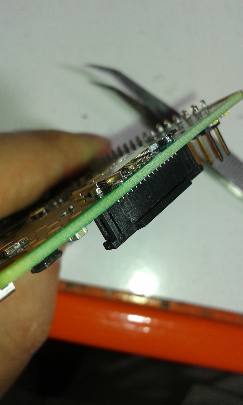
I started to wonder if this would be possible with a USB-C socket with one edge of the PCB inserting into the USB-C plug connector directly. I did a quick Google search and was very surprised that this seemed as though it hadn't been done before. 😏

Next task was to do a deep dive into the USB 3.1 spec sheet 
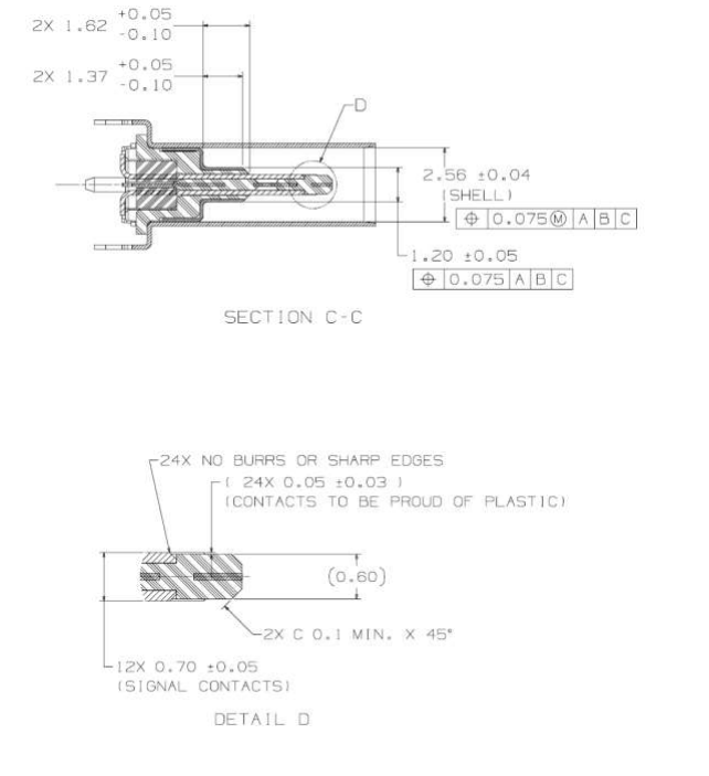
And there it was the "tongue" of the USB-C receptacle is 0.6mm wide wit the contacts proud of the Plastic or in my case PCB. 

Wondered if 0.6mm PCB would break the bank in production costs so it was time to have a search around. My usual stop now for PCBs is JLCPCB. Is I went and had a quick look to see that it wouldn't cost the earth to at least experiment and see if this is viable.
Surprising enough that even with a lead-free finish it would only cost £6 including shipping, at least to do some experimenting.

Even if I ordered V-cut panels which would give me 90+ pieces they would cost less than £0.13 each. 


It was slightly shocked at how the price jumped when I selected my usual black solder mask finish, with a large "Special Process Fee". That would certainly blow the budget feels like I'm ordering boards in 2013 again 😅. Looks as though I want to be able to sell these at a reasonable price then they will have to be green.

With my mind made up it was back to the USB-C spec sheet.
Time to fire up KiCAD and get on with creating the part.

It took a bit of drawing but here is. there is something that I found frustrating within KiCAD. this is I couldn't find a way to draw on the edge cut layer in the footprint editor. Not entirely sure if it is something I missed but decided to draw the board edge into the user drawing layer that I can copy over later.


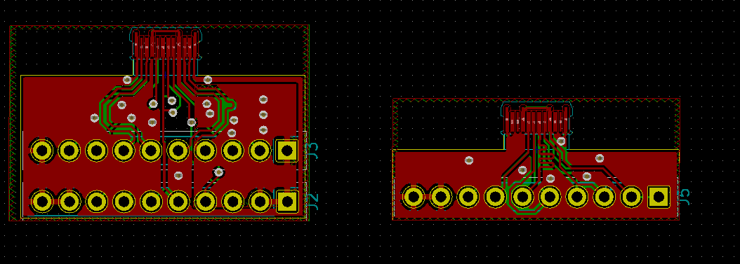
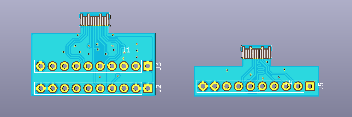
At the end of the day, I just want to see if this is a workable design so decided that making a breakout is the best plan. 


So far I have done two designs the one on the left has all 24 pins broken out for USB-SS and the right one is just for up to USB-HS. All the highspeed lined have their differential traces matched in length but the SS traced don't have the required supporting hardware, caps and filtering etc.

It was around this time i started to tell people what I was up to at which point I found there have been a few previous attempts at this type of connector.


I'm not put off exploring this path however I still think this could be a viable option could do with some tweaks in the long run. The other reason for continuing this is I don't think this option has been completely explored of documented yet.

At this point, I'm making some final tweaks to this design and hopefully sending off for production next month.

If you are interested in exploring this concept yourself all my Kicad files are available on Github so feel free to use them as you desire.

Footprint file: https://github.com/rabid-inventor/Kicad-assets/blob/master/footprint.pretty/usb-c-pcb.kicad_mod

Breakout Design: https://github.com/rabid-inventor/UBSC_PCB_Socket_Adaptor


Monday, 25 May 2020

CHUSBIE552 The CH552 Development board

For a few years I have been looking at different MCUs with USB capabilities in most cases there are not many sub $1 parts that fit the bill.

If you want something small and discreet that does a few USB functions there isn't much around, normally the barrier to entry on these types of MCUs 8 bit and 32 bit included is over the $2 mark. The issue start to become when costing the bill of materials $2 on the BOM becomes $8 by the time you get to retail price.

There are a few low cost MCUs out there like the range from STC or Nuvoton once you add a USB transceiver the cost seems to double.

I know it sees to be very focused cost but with companies form overseas being able to produce USB devices with the low retail price there must be some solution out there.

My over all goal is to demystify USB and develop a platform that gives developers confidence to develop USB devices without large overheads or in some cases complicated stacks that are beyond comprehension.

I have spoken about my admiration of the CH55x range from WCH that are a series of ultra low cost micro controllers with USB in some of the range is down in the $0.25 category in volume. Which is unbelievable a full capable MCU for the same as a discreet logic IC.

As well as the USB2.0 transceiver and the E8051 processing core itself they come with a resonable array of peripherals as well 2 x UART port, SPI  , 4 channel 8 bit ADC and 10k to 64k flash space in the case of the CH559.

There are a few dev boards out there for the CH55x range mainly from electrodragon with their CH55x range of boards. They are a nice range but I feel they have a couple of  points that I would love to see improved on. 

This is why I decided to start the CHUSBIE range starting with the CHUSBIE552 based on the CH552T or CH552G a lower cost less IO version.


With the CHUSBIE552 I have added onboard functions that I think will be the most useful to a developer like: 
  • onboard reset and bootloader buttons
  • RX and TX indicator LEDs
  • sensible pin-outs with pins and ports in order
  • optional landing for external XTAL crystal for precision timing applications 
  • Power indicator LED

I would like to see a general adoption of the CH55x range chips in a similar way to the ESP8266 and ESP32 (notably neither of which have native USB which in my humble option would be a killer addition).

I want to work on the software stacks to make them more friendly for a start making sure the Chinese comments are translated to English for the examples especially the USB ones. My point is that USB doesn't need to be this mystical black box that can't be easily accessed by most hobbyists and makers.

So far in my research I found firmware for USB CDC device, USB HID device and USB JTAG device all of which i am trying out to incorporate into a master repository.

Updates to this project can be found here:

https://hackaday.io/project/171543-chusbie552-ch552-development-board

I hope to have the completed board available on my Tindie store here:
https://www.tindie.com/stores/rabidselectronicsemporium/


Monday, 30 May 2016

'Circuits, Art and Hacks' My experience of Boldport Club Membership

Beer or Beautiful circuits mmmmmm........

A few moths back there was some musings going around the twitterverse from one Saar Drimer of Boldport. It went something along the lines of:

'I'm thinking of starting something but would people pay good money for beautiful circuits'

This is the though that started The Boldport Club.

Boldport is an electronics design firm headed up by Saar focused on designing boards that are both beautiful and functional some of his designs including The Seahorse, The Life Game and The Cordwood Puzzle. Saar's PCB designs are both beautiful and unique, using every layer of the PCB to give the greatest impact including designs by exposing the copper layer and using back lighting to highlight otherwise invisible design features.

The Boldport Club is a subscription service setup by Saar for people to own their own piece of these beautifully designed circuits. These subscription costs £49 for a three months that's inclusive of taxes and shipping. The circuits are combinations of solder at home kits and single beautiful boards.

My first kit arrived a week ago and I have been itching to put it together. 


The first kit is the Pease board this is a tribute to Bob Pease a renowned designer at National Semiconductors and quoted on the front of the packaging 'My favorite programming language is solder' which makes me smile every time I hear it. The circuit provided is a light intensity to frequency converter based on the LM331 which was one of the famous ICs designed by Bob Pease.

The kit is stunningly well packed in a laser cut corrugated cardboard sandwich the amount of thought that has gone into to overall out of the box experience is breathtaking. I felt guilty opening it as it would destroy the packaging.


The story continues on opening the packaging every part feels well thought through.


The surprise in this kit is you are supplied with two PCBs I'm assuming one to make and other one is to keep as a key ring.

On close inspection of the PCB there are visible SMT pads for soldering surface mount components. Well me being me decides that I'm going to make my Pease board surface mounted. Time to find that tube of solder paste.


Surface mounted components describe components that have been soldered on top of the surface of a PCB instead of 'Through hole' or PTH the component leads pass through the board and are soldered from the opposite side of the PCB. It is very possible to hand solder SMT parts to a board in fact I do it regularly with my work, but if a reflow oven is available then applying the solder paste to the pads placing the components on the paste and melting the solder in the reflow oven is far simpler.


I unfortunately didn't have exact values for some of the components so I had to swap some values around.

330pF  ->  220 pF Capacitor

6.81kOhm -> 5.1kOhm Resistor

also used a Fairchild BSS138 for the drive circuit and a blue 0805 ultra bright LED.

I'm not sure what sort of effect this will have on the operation of th LM331 for pouring over the datasheet these components appear to control the frequency range.


So Here I am with the component soldered down nicely. The BSS138 seemed to be the wrong package type for this landing but the connections look secure.


Woot! it works. I found with mine that there was not much difference in the LED output but the oscilloscope told a much different story.

We if I can't get it to vary the LED brightness then just maybe I can get it to sing. So using the 3 watt amp from a Pimoroni Picade PCB, I Made a singing Pease Board/Theremin. 


So final thoughts on the Boldport club, I am really enjoying the kits that are coming through my door each month, the give me some new outlooks into circuit design and I can't wait to see what comes next.

If you what to become a member head over to www.boldport.club.
Thursday, 21 January 2016

A first look at the SeeedStudio Rephone

I have had an exciting kickstarter reward arrive. My Seeedstudio RePhone has landed and I am having a little play with it to see what it is like.


SeeedStudio are a maker supplies firm based in Shenzhen, china would make some very nice maker goodies at an affordable price. I met some of the guys from SeeedStudio while out in Berlin during my #HackAroundBerlin tour, and found that they were holding a Hackday in the city at BetaHaus for there new kickstarter the RePhone.


The Rephone is and Open Source modular cellular phone system that has a central GSM and BLE module that is programmable via the Arduino IDE. The tier that I backed on kickstarter was the Create Kit which as well as the main Rephone module it includes a touchscreen module, a speaker and microphone module and a Prototyping module. 


I was excited to get it open and show you guys what it includes. Hopefully this is a better quality video than previous, I have a new camera and microphone as the overall quality should be better.

Monday, 6 July 2015

Hacking the RyanTecK Debug Clip

I recently Acquired a RyanTeck Debug clip and in a previous blog post I assembled and set it up.

It work brilliantly with the Raspberry Pi but I would like to use it in some of my other projects and put it through its paces or at least the USB bridge IC the MCP2221 by Microchip.

The first thing I want to do is hit the data sheet and see what other functions the MCP2221 is capable of.

OK, Ryan Tech I have to admit this chip is really cool I hadn't noticed that it has an onboard ADC as well. This is all on top of the standard GPIO, UART and I2C capabilities. 

Hack #1 


Soldering a header into the the debug clip. This is mainly so I am able to use jumper wires to hook it up to other devices. 

For me I find female socket most useful for the stuff I like to mess with. This just allows to make the connections  mainly the first one being connecting the power so the debug clip can run without being attached to the raspberry pi.

Hack #2 


Powering The debug clip without a raspberry pi. The Debug clip has a voltage fail safe mainly for the Raspberry  Pi. The MCP2221 runs from the 3v3 voltage rail of the RasPi but this also means it will not run on its own. 


This is fixed by using a a jumper wire between the 5v connection and the 3v3 .

WARNING: This will mean the debug will be running at 5v do not connect to the RasPi's or other 3v3 devices GPIO It could damage it. This is why I use the socket and jumper wire without soldering at the moment. 

Hack #3


This is a bit of a dirty hack to get the 3v3 power onboard. I have a few  AP1117 LDO 3v3 voltage regulators. I'm going to hack one onto the underside of the board this will give me a selectable  3.3volt supply.


A few flying decoupling caps as recommended in the application notes. A bit of jump leading on the to and all is well.


Now the UART is running at 3v3 again without a raspberry pi. and now running with a Ublox Neo-6M GPS module.


With some nice tangible data returning to putty. I'm doing this indoors so I don't have a GPS fix but the data connection  work very well.

Further hacks


There will be more hack coming with the debug clip like changing its function and using the I2C interface, and this little device is sure to make an appearance as useful tool in future posts.

Happy Hacking  :)


Tuesday, 23 June 2015

Dirty Hack: repairing (Breaking it better) a raspberry A+,B+ or 2 microSD card Socket

This is just a quick and dirty hack that i have had to perform once in a while. Sometimes and I have to say this problem is quite rare the catch that holds the microSD card in the socket fails and it is impossible to get the card to stay in place.


I have had this problem passed over my desk a few times I have a little fix/break for this that works.

WARNING: ONLY TRY THIS AFTER EXHAUSTING ALL OTHER POSSIBILITIES OF REPLACEMENT OR REPAIR AS YOU WILL BE DAMAGING THE MIRCO SD CARD SOCKET FOR THIS TO WORK. THERE IS NO GUARANTEE THIS WILL NOT RENDER YOUR RASPBERRY PI MORE BROKEN THAN IT ALREADY WAS :)  I TAKE NO RESPONSIBILITY FOR BROKEN RASPBERRY PIs

So basically we are going to remove the catch and spring that retains and ejects the SD card. Hopefully without damaging the contacts.


Use some good sharp tweezers to lift the the tab of metal housing at the edge of the Raspberry Pi.


Once that is lifted then used the tweezers to hook out the the plastic catch and spring.


Then it is just a case of folding the tab back down again and squeezing the housing slightly so that it applies some pressure on the SD Card when it is inserted.


After that it should be a case of sliding in the SD card and powering up if you have done this right the Pi should boot.


I normally add a little tape over then in SD card just to make sure it don't knock it out.

Hope this helps some people out as mentioned at the beginning you are essential breaking the socket to fix it.