CHUSBIE552

Showing posts with label Soldering. Show all posts

Monday, 30 May 2016

'Circuits, Art and Hacks' My experience of Boldport Club Membership

Beer or Beautiful circuits mmmmmm........

A few moths back there was some musings going around the twitterverse from one Saar Drimer of Boldport. It went something along the lines of:

'I'm thinking of starting something but would people pay good money for beautiful circuits'

This is the though that started The Boldport Club.

Boldport is an electronics design firm headed up by Saar focused on designing boards that are both beautiful and functional some of his designs including The Seahorse, The Life Game and The Cordwood Puzzle. Saar's PCB designs are both beautiful and unique, using every layer of the PCB to give the greatest impact including designs by exposing the copper layer and using back lighting to highlight otherwise invisible design features.

The Boldport Club is a subscription service setup by Saar for people to own their own piece of these beautifully designed circuits. These subscription costs £49 for a three months that's inclusive of taxes and shipping. The circuits are combinations of solder at home kits and single beautiful boards.

My first kit arrived a week ago and I have been itching to put it together. 


The first kit is the Pease board this is a tribute to Bob Pease a renowned designer at National Semiconductors and quoted on the front of the packaging 'My favorite programming language is solder' which makes me smile every time I hear it. The circuit provided is a light intensity to frequency converter based on the LM331 which was one of the famous ICs designed by Bob Pease.

The kit is stunningly well packed in a laser cut corrugated cardboard sandwich the amount of thought that has gone into to overall out of the box experience is breathtaking. I felt guilty opening it as it would destroy the packaging.


The story continues on opening the packaging every part feels well thought through.


The surprise in this kit is you are supplied with two PCBs I'm assuming one to make and other one is to keep as a key ring.

On close inspection of the PCB there are visible SMT pads for soldering surface mount components. Well me being me decides that I'm going to make my Pease board surface mounted. Time to find that tube of solder paste.


Surface mounted components describe components that have been soldered on top of the surface of a PCB instead of 'Through hole' or PTH the component leads pass through the board and are soldered from the opposite side of the PCB. It is very possible to hand solder SMT parts to a board in fact I do it regularly with my work, but if a reflow oven is available then applying the solder paste to the pads placing the components on the paste and melting the solder in the reflow oven is far simpler.


I unfortunately didn't have exact values for some of the components so I had to swap some values around.

330pF  ->  220 pF Capacitor

6.81kOhm -> 5.1kOhm Resistor

also used a Fairchild BSS138 for the drive circuit and a blue 0805 ultra bright LED.

I'm not sure what sort of effect this will have on the operation of th LM331 for pouring over the datasheet these components appear to control the frequency range.


So Here I am with the component soldered down nicely. The BSS138 seemed to be the wrong package type for this landing but the connections look secure.


Woot! it works. I found with mine that there was not much difference in the LED output but the oscilloscope told a much different story.

We if I can't get it to vary the LED brightness then just maybe I can get it to sing. So using the 3 watt amp from a Pimoroni Picade PCB, I Made a singing Pease Board/Theremin. 


So final thoughts on the Boldport club, I am really enjoying the kits that are coming through my door each month, the give me some new outlooks into circuit design and I can't wait to see what comes next.

If you what to become a member head over to www.boldport.club.

Sunday, 22 May 2016

SHED SHORT: Why I Have a Gripe with Standard Sizes of LEDs

After filming my first Rabid Inventor in a Shed video realized there where a few handy hits and tips that could get lost in the middle of it.

So I have at started SHED SHORTS which focus on these tips.


Had to start with a bit of moan and why I have a problem with 3mm, 5mm and 10mm LEDs, and what I do to get around this. I'll show you an easy way to solder 0805 SMD LEDs onto perfboard, and ended up building a Larson scanner.

I used the code from this inscrutable by samlynn79 to get the Larson scanner running.

Hope You Enjoy.

Tuesday, 17 May 2016

Sheds and Circuit Beauty

Arriving on my doorstep was the next installment if my Boldport Club subscription.


The Cordwood Puzzle is Boldport's own tribute to Cordwood circuit design. So time to break my Shed this is part of a new video series 'Rabid Inventor In A Shed'. Everyone needs a workshop-shed so spent some time kitting out mine, and it was about time to break it in.

Its Not Much But Its Mine 

With Integrated Drone Parking 


Monday, 6 July 2015

Hacking the RyanTecK Debug Clip

I recently Acquired a RyanTeck Debug clip and in a previous blog post I assembled and set it up.

It work brilliantly with the Raspberry Pi but I would like to use it in some of my other projects and put it through its paces or at least the USB bridge IC the MCP2221 by Microchip.

The first thing I want to do is hit the data sheet and see what other functions the MCP2221 is capable of.

OK, Ryan Tech I have to admit this chip is really cool I hadn't noticed that it has an onboard ADC as well. This is all on top of the standard GPIO, UART and I2C capabilities. 

Hack #1 


Soldering a header into the the debug clip. This is mainly so I am able to use jumper wires to hook it up to other devices. 

For me I find female socket most useful for the stuff I like to mess with. This just allows to make the connections  mainly the first one being connecting the power so the debug clip can run without being attached to the raspberry pi.

Hack #2 


Powering The debug clip without a raspberry pi. The Debug clip has a voltage fail safe mainly for the Raspberry  Pi. The MCP2221 runs from the 3v3 voltage rail of the RasPi but this also means it will not run on its own. 


This is fixed by using a a jumper wire between the 5v connection and the 3v3 .

WARNING: This will mean the debug will be running at 5v do not connect to the RasPi's or other 3v3 devices GPIO It could damage it. This is why I use the socket and jumper wire without soldering at the moment. 

Hack #3


This is a bit of a dirty hack to get the 3v3 power onboard. I have a few  AP1117 LDO 3v3 voltage regulators. I'm going to hack one onto the underside of the board this will give me a selectable  3.3volt supply.


A few flying decoupling caps as recommended in the application notes. A bit of jump leading on the to and all is well.


Now the UART is running at 3v3 again without a raspberry pi. and now running with a Ublox Neo-6M GPS module.


With some nice tangible data returning to putty. I'm doing this indoors so I don't have a GPS fix but the data connection  work very well.

Further hacks


There will be more hack coming with the debug clip like changing its function and using the I2C interface, and this little device is sure to make an appearance as useful tool in future posts.

Happy Hacking  :)


Thursday, 18 June 2015

Ryan Tech Debug Clip (Assembly)

I was passed a Ryan Tech Debug Clip, a little board that allows you to connect to a Raspberry Pi via USB and the UART connections on it's GPIO this was due a good friend of mine Gadgetoid  had 2  from backing the Kickstarter.

I got interested in this watching Gadgetiod solder up the realising that it wasn't just another FTDI FT232R (being honest no happy with them after the hole bricking your device scandal, long story) or a Prolific PL-2303. It was using something unexpected Microchip MCP2221.

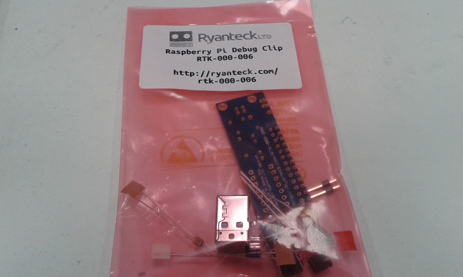
This little chip is not only a basic USB to UART bridge it can also bridge to GPIO, I2C and a tonne of other functionality. This really peaked my interest but that will be for a later blog post. This post i'm looking the assembly and what comes in the kit.

The Debug Clip clip comes in kit form requiring soldering together don't be too put off by this as all the joints are well spaced and it has plenty of guidance on the PCB's silkscreen.


In the kit is:

  • PCB 
  • A USB Type B socket 
  • A two pin header with jumper 
  • A green and a red LED
  • A diode 
  • Two Resistors of the same value 
  • A fuse
  • And the MCP2221 IC itself

One thing to note there was ESD foam protection on the legs of the IC. The foam would offer some electrical protection but the main reason would be to prevent the legs from being damaged in shipping.


The kit feels well thought through, the silkscreen on the PCB makes assembly even easier. There is a clear assembly guide provided by Ryan Tech but the Silk was so clear I didn't even need to look at it.

Assembling 


There are only a few things to make sure the orientation is correct the IC, the diode and the two LEDs.


I started assembling mine with the diode and resistors the have the lowest height to the board and folded the legs outwards before soldering. Then solder and trim with some side cutters.


The IC itself was next in height order it always worth making sure that the notch on the IC matches the pattern on the silkscreen.


Next I decided the the USB socket would be the best as it would create a flat surface to rest on this help with supporting the header when soldering that in, making sure to solder one contact on the header first and then reheat the join and push the part flush with the PCB (Mind you fingers it could get hot) 

Then it was onto the LEDs I chose the green one for RX and the red for TX. The positions are well marked with a little + for the positive side, which is the longer of the two LED leads.


The last component I assembled was the fuse then all was done for the moment.


All ready to plug into your Raspberry Pi and PC's USB port.

Installing drivers 

The Debug Clip's driver are not available in windows update at the moment but can be easily downloaded from the Microchip MCP2221 Product page.


If the device is working correctly it will appear in your device manager as other devices -> MCP2221 USB-I2C/UART Combo. Please note that the Clip will not work unless placed on a the Raspberry Pi's GPIO header, as it uses the Pi's 3.3v regulator to make sure the UART output is 3.3v so it doesn't damage the Pi. Also make sure that the Pi is on. 

So now go ahead and download the appropriate driver for you. I'm running a Windows 8.1 laptop so mine is the Windows Driver & Installer. 

Once downloaded open the archive and extract the files.


Navigate through the Driver Installation Tool and relevant 32 or 64 bit version and right click on the .inf file and select install from the menu. ( for me the installation tool didn't work )


 Then the device should appear in your device manager. This would be a really good point to  take note of which COM port the Clip appears on. (In my case it is assigned to COM10).

Using the Debug Clip

You are going to need a remote terminal program if you don't have one already, I use Putty and would recommend it for most users. I can be downloaded form here.

Once you have Putty running click on the Serial radio button and enter your COM number that you noted earlier and set the speed to 115200.


After clicking open a terminal window should appear and you will be asked to login with the normal user name a password.


Then you can just use it as though you are on the Raspberry Pi's command line.

I like the Debug Clip and it is nice to have the blinking green and red LEDs as the data is going back and fourth. It makes a good alternative to the FTDI or Prolific based boards that are out there. the assembly we very straight forward with no real issues. I give it 4 sparks, 3 for the device and and bonus for hack-ability. 


Then next Post do will be about modding and hacking the Debug Clip.


Sunday, 24 May 2015

Pi Supply Gert VGA666 Assembly

So i have had this rocking around for some time now and I though it was high time that i gave it a test run.

This is the Gert VGA666 from Pi Supply. Designed a by Gert Van Loo of Raspberry Pi fame and ran as a successful kickstarter campaign back in October 2014 ( which is where mine has come from ).

The Gert VGA666 is a clever breakout board for the Raspberry Pi that allows it to use the GPIO header to generate a VGA signal.  This done with only 20 Resistors to mimic an analog signal  the VGA monitor use the obvious downside to this is that you use up a lot of the GPIO pins.

 Assembly       

On the Pi Supply product Page there is a link to a Github Repository that contains the instructions, some of the details on how it works and the required files to make the Pi work with it .


This is the what comes in the Kit:
  • PCB 
  • 20 Resistors 
  • VGA socket 
  • extended GPIO Connector 
  • 2 Stickers and a Business card directing you towards the Pi Supply Website 
 This first thing I recommend doing is layout the parts and use a multimeter to check and label the tapes of resistors with all their values on the blue cased film resistor I find the colours hard to distinguish so i usually go straight for the multimeter as better choice than tying to remember my resistor band colours.


Labeling just helps when you come to the placing the parts. there should be:

  • 2 x 120 ohm
  • 3 x 500 ohm
  • 3 x 1K ohm
  • 3 x 2K ohm 
  • 3 x 4K ohm
  • 3x  8K ohm 
  • 3 x 16K ohm 

I find the colour key in the instruction a little hard to follow so here is a Bill of Materials for the Resistors.
 Label            Resistance (ohms)
R2 -          500
R4 -          1000
R6 -          2000
R8 -          4000
R10 -        8000
R12 -        16000
R14 -        500
R16 -        1000
R18 -        2000
R20 -        4000
R22 -        8000
R24 -        16000
R26 -         500
R28 -        1000
R30 -        2000
R32 -        4000
R34 -        8000
R36 -        16000
R38 -          120
R40 -          120

Then it is just a case of placing all the resistors in their correct locations and fold the leads outward for me I like to place all the resistors first as this lest me see if I have any location wrong before soldering.


The back of the PCB becomes a bit of a 'Rats Nest' of resistor leads but there is plenty of space to solder them form the topside.


After soldering use a sideways cutter to trim all the leads if and if there are any joins looking a little low on solder apply more (best to do this as a better solder joint will give a more stable signal).


 now make sure the PCB is the correct way up for the next bit the instructions say 'The Connectors are at the same side as the surface mount resistors'

Then it is just a case of soldering first the GPIO connectors soldering one corner pin first to make sure that it is flush to the board then solder the rest of the pins you can insert the VGA connector if it makes the PCB a bit more stable to solder for you.

Then solder up the VGA connector.

ALL Assembled!

I will continue the software setup and testing in another post. Click Here