CHUSBIE552

Showing posts with label electronics. Show all posts

Monday, 20 April 2020

Restarting the YouTube channel

It's been a while and I have decided that it was time to restart the YouTube channel.

I decided a few months ago it was time to start again to try and make some content more in reflection of how my life is now, this is because a lot of the content was well over 5 years old and in some cases much older.

I want to try and make this channel great and informative from the beginning and with help from my beautiful supportive wife 💗 I believe this is possible.

Onto the first video (don't get too excited it is just a channel update) 😊 but I have spent some time on the title sequence and eventually should have an ending sequence.The music by the way is free for non commercial use from fesliyanstudios so a big special thanks to them for providing that free for use as I believe it really works for my content.


I have several open projects that I started this year and I'm hoping to keep you in the loop and up to date on.

SimpleJTAG (low cost JTAG programmer)
Basic-MC6800 (Retro computer board)
Rabid's Electronics Emporium (My Tindie Store)
GOWIN GN1SE board
CH552 Dev board ( Yet to come up with a good name )

My filming schedule:
I am hoping that I can release two videos a month or a video every two weeks.

Let me know what you think either down below, twitter or Hackaday.io 

Ta Ta For Now


Tuesday, 17 May 2016

Sheds and Circuit Beauty

Arriving on my doorstep was the next installment if my Boldport Club subscription.


The Cordwood Puzzle is Boldport's own tribute to Cordwood circuit design. So time to break my Shed this is part of a new video series 'Rabid Inventor In A Shed'. Everyone needs a workshop-shed so spent some time kitting out mine, and it was about time to break it in.

Its Not Much But Its Mine 

With Integrated Drone Parking 


Thursday, 21 January 2016

A first look at the SeeedStudio Rephone

I have had an exciting kickstarter reward arrive. My Seeedstudio RePhone has landed and I am having a little play with it to see what it is like.


SeeedStudio are a maker supplies firm based in Shenzhen, china would make some very nice maker goodies at an affordable price. I met some of the guys from SeeedStudio while out in Berlin during my #HackAroundBerlin tour, and found that they were holding a Hackday in the city at BetaHaus for there new kickstarter the RePhone.


The Rephone is and Open Source modular cellular phone system that has a central GSM and BLE module that is programmable via the Arduino IDE. The tier that I backed on kickstarter was the Create Kit which as well as the main Rephone module it includes a touchscreen module, a speaker and microphone module and a Prototyping module. 


I was excited to get it open and show you guys what it includes. Hopefully this is a better quality video than previous, I have a new camera and microphone as the overall quality should be better.

Saturday, 10 October 2015

#HackAroundBerlin Tour Of The Berlin FabLab

My #HackAroundBerlin continues with a visit to the Berlin Fab Lab. This place is a product developers dream with a laundry list of high end prototyping equipment, from 3D printers and lasercutters all the way up to a full on CNC mill.


Special thanks has to go to the guys at the Space Sylvester, Laslow, Rose, Erick and Murat for making me so welcome.


The main public area 

Wood working area

Heavy Metal Lab

Composites Lab

These are little Lasercut models that the FabLab created to give away at Maker Faire Berlin  


Sunday, 5 July 2015

What makes a DHT11 temperature humidity sensor Tick

A DHT11 is very low cost and well supported temperature and relative humidity I've had a few of these for a while and always wondered how they work. I think its time for a TEARDOWN.


There are a lot manufactures for the DHT11 this one is made my AOSONG. It can run between between 3 and 5 volts and uses a simple one wire protocol to communicate with other devices. For more details on the sensor itself check out the datasheet.


The casing is in two parts so to get inside it is just a matter of getting a sharp knife and splitting the case apart.


Inside the case is a small PCB with a SOIC 14 packaged IC unfortunately the part number has been removed so there is really no way to tell if this is a custom part or a specially programmed MCU. along the edge of the IC are couple of  ceramic capacitors for decoupling and noise suppression, and some other misc passive components. The green resistor I can assume is a precision resistor for the humility sensor (explained in more detail later).  


On the other side the sensor hardware itself. This consists of a PCB with interlaced traces that creates capacitance this with change based on the amount of moisture present in the air around it.  


HOW DOES IT WORK

The interlaced +ive and -ive traces allow a small amount of charge to be stored in each of the traces allowing the circuit to charge up a little, this is called capacitance and this is effected by the material separating the +ive and -ive which is mostly air and its airs permittivity one of the factors for calculating capacitance is affected by temperature and humidity. 
So the chip uses the precision resistor I mentioned earlier and measures the discharge time through that resistor to calculate the capacitance, and then uses that figure used with the internal temperature sensor inside the main IC to calculate the relative humidity.
    

Tuesday, 23 June 2015

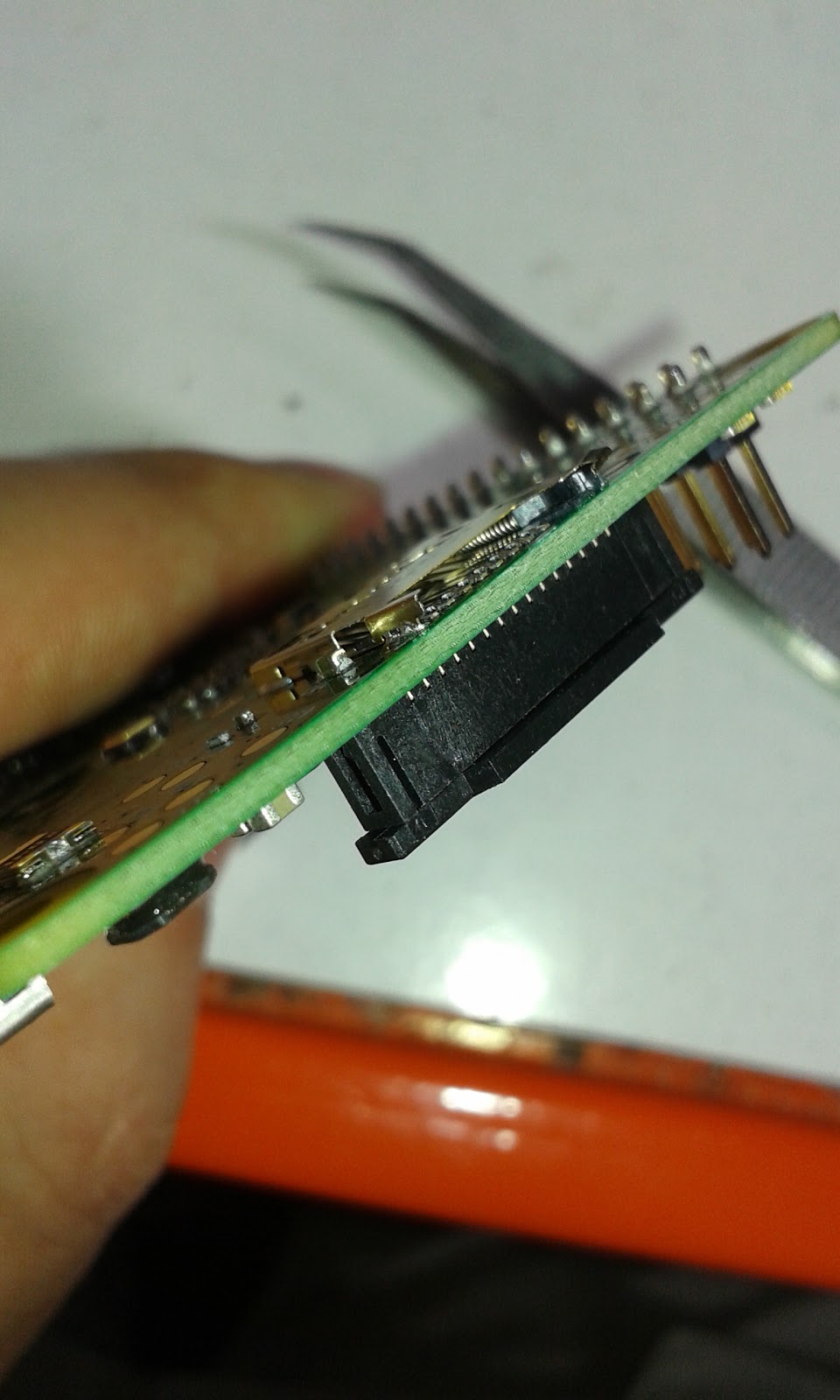
Dirty Hack: repairing (Breaking it better) a raspberry A+,B+ or 2 microSD card Socket

This is just a quick and dirty hack that i have had to perform once in a while. Sometimes and I have to say this problem is quite rare the catch that holds the microSD card in the socket fails and it is impossible to get the card to stay in place.


I have had this problem passed over my desk a few times I have a little fix/break for this that works.

WARNING: ONLY TRY THIS AFTER EXHAUSTING ALL OTHER POSSIBILITIES OF REPLACEMENT OR REPAIR AS YOU WILL BE DAMAGING THE MIRCO SD CARD SOCKET FOR THIS TO WORK. THERE IS NO GUARANTEE THIS WILL NOT RENDER YOUR RASPBERRY PI MORE BROKEN THAN IT ALREADY WAS :)  I TAKE NO RESPONSIBILITY FOR BROKEN RASPBERRY PIs

So basically we are going to remove the catch and spring that retains and ejects the SD card. Hopefully without damaging the contacts.


Use some good sharp tweezers to lift the the tab of metal housing at the edge of the Raspberry Pi.


Once that is lifted then used the tweezers to hook out the the plastic catch and spring.


Then it is just a case of folding the tab back down again and squeezing the housing slightly so that it applies some pressure on the SD Card when it is inserted.


After that it should be a case of sliding in the SD card and powering up if you have done this right the Pi should boot.


I normally add a little tape over then in SD card just to make sure it don't knock it out.

Hope this helps some people out as mentioned at the beginning you are essential breaking the socket to fix it.

Sunday, 24 May 2015

Pi Supply Gert VGA666 Assembly

So i have had this rocking around for some time now and I though it was high time that i gave it a test run.

This is the Gert VGA666 from Pi Supply. Designed a by Gert Van Loo of Raspberry Pi fame and ran as a successful kickstarter campaign back in October 2014 ( which is where mine has come from ).

The Gert VGA666 is a clever breakout board for the Raspberry Pi that allows it to use the GPIO header to generate a VGA signal.  This done with only 20 Resistors to mimic an analog signal  the VGA monitor use the obvious downside to this is that you use up a lot of the GPIO pins.

 Assembly       

On the Pi Supply product Page there is a link to a Github Repository that contains the instructions, some of the details on how it works and the required files to make the Pi work with it .


This is the what comes in the Kit:
  • PCB 
  • 20 Resistors 
  • VGA socket 
  • extended GPIO Connector 
  • 2 Stickers and a Business card directing you towards the Pi Supply Website 
 This first thing I recommend doing is layout the parts and use a multimeter to check and label the tapes of resistors with all their values on the blue cased film resistor I find the colours hard to distinguish so i usually go straight for the multimeter as better choice than tying to remember my resistor band colours.


Labeling just helps when you come to the placing the parts. there should be:

  • 2 x 120 ohm
  • 3 x 500 ohm
  • 3 x 1K ohm
  • 3 x 2K ohm 
  • 3 x 4K ohm
  • 3x  8K ohm 
  • 3 x 16K ohm 

I find the colour key in the instruction a little hard to follow so here is a Bill of Materials for the Resistors.
 Label            Resistance (ohms)
R2 -          500
R4 -          1000
R6 -          2000
R8 -          4000
R10 -        8000
R12 -        16000
R14 -        500
R16 -        1000
R18 -        2000
R20 -        4000
R22 -        8000
R24 -        16000
R26 -         500
R28 -        1000
R30 -        2000
R32 -        4000
R34 -        8000
R36 -        16000
R38 -          120
R40 -          120

Then it is just a case of placing all the resistors in their correct locations and fold the leads outward for me I like to place all the resistors first as this lest me see if I have any location wrong before soldering.


The back of the PCB becomes a bit of a 'Rats Nest' of resistor leads but there is plenty of space to solder them form the topside.


After soldering use a sideways cutter to trim all the leads if and if there are any joins looking a little low on solder apply more (best to do this as a better solder joint will give a more stable signal).


 now make sure the PCB is the correct way up for the next bit the instructions say 'The Connectors are at the same side as the surface mount resistors'

Then it is just a case of soldering first the GPIO connectors soldering one corner pin first to make sure that it is flush to the board then solder the rest of the pins you can insert the VGA connector if it makes the PCB a bit more stable to solder for you.

Then solder up the VGA connector.

ALL Assembled!

I will continue the software setup and testing in another post. Click Here


Saturday, 24 January 2015

The Challenge (Pimoroni vs Oomlout vs DoESLiverpool)

So in Sheffield we have just had an Open Source Hardware User Group event that brought a few makers, maker business owners, open source enthusiasts and social enterprises together.

Now after the event on Open Source Business we all adjourned to the Rutland Arms for a quick one before home.
Well that many Makers and Tech nerds in the same building it was bound to happen.  

A CHALLENGE between myself of Pimoroni,  Oomlout and DoES Liverpool 

The Challenge:

To build a device that can propel small light weight projectiles against a target. The ammunition can be chosen between from:

  • Nerf Darts 
  • Ping Pong Balls 
  • Ball Pool Balls 
Design Constants:

Apart from of the shelf fixtures and fittings and available motors etc. the device can be made from no more then a single sheet of A0 (1200mm x 900mm) 3mm acrylic. Must be ready by MakerFaire UK.

Winning Conditions:

The greatest number of projectiles hitting against a target in 30 seconds.


I'll keep you up to date in my progress :) already have a few ideas 


Saturday, 17 January 2015

Flotilla The NEW making tinkering platform for the Raspberry Pi by Pimoroni

Kickstarter is all a buzz with excitement as Pimoroni launch their new campaign.


Flotilla is a brand new development platform for the Raspberry Pi with a focus on 'Hassle-free Digital tinkering for everyone'

Flotilla consists of a Dock that different Modules plug into consisting of sensors, controls motors and displays.


The Platform is designed to be used by everyone from a young beginner to hardened maker with programming systems from basic suggested 'Cookbook' projects ,a webpage icon based programming interface called 'Rockpool' to well supported Scratch implementations and python Modules.


At the writing of this post The Campaign was over 1/2 funded within a few hours at over £16500 and 191 Backers :)

This is a fantastic project that, if executed right will make entry into tinkering with electronics so much easier, removing the need to understand wire protocols and endless debugging, and just getting on with being creative.

UPDATE: 
As of around 9.30am 18/01/15 Flotilla reached its campaign goal of £32,768 it has really raced through hitting its goal in just over 24hrs, and at writing this update was most of the way to £40K.

This is an incredible pace and hopefully there will be many stretch goal to keep new backers clocking in, It is made even more incredible because it has only been advertised through twitter and Bloggers like myself Mike Horne and a few others (sorry if I haven't listed you, I can only find this one at the mo ;) ) .

At this point  Kickstarter prediction engine Kicktraq predicts based on current trend could reach just shy for £600,000 by the end of the campaign.

Watch and see :)