CHUSBIE552

Showing posts with label hacks. Show all posts

Friday, 31 July 2020

USB-C an Experiment

USB-C is more and more becoming a standard in the maker community for power supply and coms with peoples creations. But there is a catch to this although the USB A plug to USB C plug cable is freely available almost everywhere, the sockets can be a little more daunting. There are not only many to choose for including some with and without through-hole pin the pitch and spacing often means you have to spin a PCB to make them work. then there are concerns with soldering them effectively. 


I started to wonder if this would be possible with a USB-C socket with one edge of the PCB inserting into the USB-C plug connector directly. I did a quick Google search and was very surprised that this seemed as though it hadn't been done before. 😏

Next task was to do a deep dive into the USB 3.1 spec sheet 
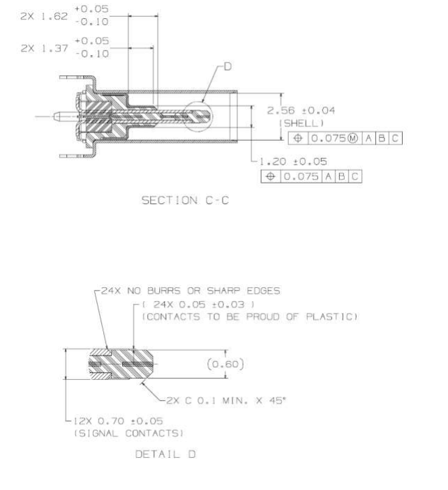
And there it was the "tongue" of the USB-C receptacle is 0.6mm wide wit the contacts proud of the Plastic or in my case PCB. 

Wondered if 0.6mm PCB would break the bank in production costs so it was time to have a search around. My usual stop now for PCBs is JLCPCB. Is I went and had a quick look to see that it wouldn't cost the earth to at least experiment and see if this is viable.
Surprising enough that even with a lead-free finish it would only cost £6 including shipping, at least to do some experimenting.

Even if I ordered V-cut panels which would give me 90+ pieces they would cost less than £0.13 each. 


It was slightly shocked at how the price jumped when I selected my usual black solder mask finish, with a large "Special Process Fee". That would certainly blow the budget feels like I'm ordering boards in 2013 again 😅. Looks as though I want to be able to sell these at a reasonable price then they will have to be green.

With my mind made up it was back to the USB-C spec sheet.
Time to fire up KiCAD and get on with creating the part.

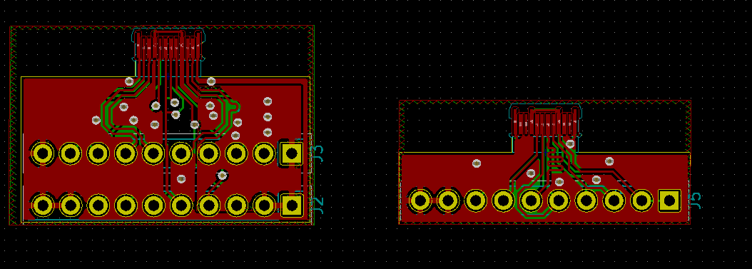
It took a bit of drawing but here is. there is something that I found frustrating within KiCAD. this is I couldn't find a way to draw on the edge cut layer in the footprint editor. Not entirely sure if it is something I missed but decided to draw the board edge into the user drawing layer that I can copy over later.


At the end of the day, I just want to see if this is a workable design so decided that making a breakout is the best plan. 


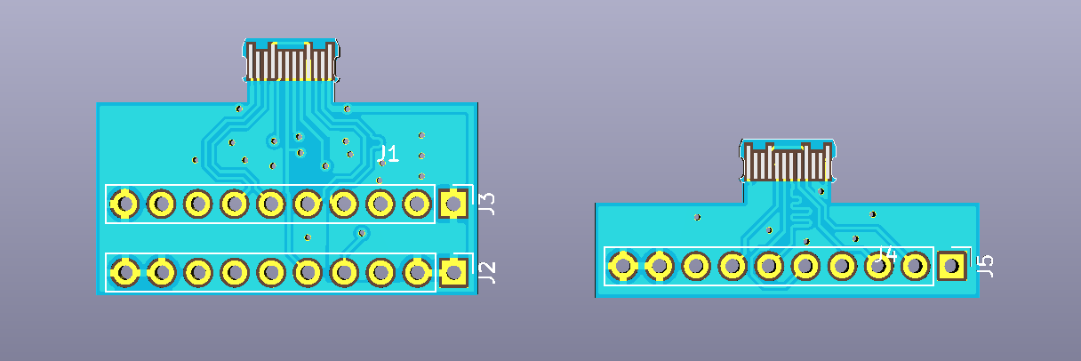
So far I have done two designs the one on the left has all 24 pins broken out for USB-SS and the right one is just for up to USB-HS. All the highspeed lined have their differential traces matched in length but the SS traced don't have the required supporting hardware, caps and filtering etc.

It was around this time i started to tell people what I was up to at which point I found there have been a few previous attempts at this type of connector.


I'm not put off exploring this path however I still think this could be a viable option could do with some tweaks in the long run. The other reason for continuing this is I don't think this option has been completely explored of documented yet.

At this point, I'm making some final tweaks to this design and hopefully sending off for production next month.

If you are interested in exploring this concept yourself all my Kicad files are available on Github so feel free to use them as you desire.

Footprint file: https://github.com/rabid-inventor/Kicad-assets/blob/master/footprint.pretty/usb-c-pcb.kicad_mod

Breakout Design: https://github.com/rabid-inventor/UBSC_PCB_Socket_Adaptor


Sunday, 22 May 2016

SHED SHORT: Why I Have a Gripe with Standard Sizes of LEDs

After filming my first Rabid Inventor in a Shed video realized there where a few handy hits and tips that could get lost in the middle of it.

So I have at started SHED SHORTS which focus on these tips.


Had to start with a bit of moan and why I have a problem with 3mm, 5mm and 10mm LEDs, and what I do to get around this. I'll show you an easy way to solder 0805 SMD LEDs onto perfboard, and ended up building a Larson scanner.

I used the code from this inscrutable by samlynn79 to get the Larson scanner running.

Hope You Enjoy.

Monday, 6 July 2015

Hacking the RyanTecK Debug Clip

I recently Acquired a RyanTeck Debug clip and in a previous blog post I assembled and set it up.

It work brilliantly with the Raspberry Pi but I would like to use it in some of my other projects and put it through its paces or at least the USB bridge IC the MCP2221 by Microchip.

The first thing I want to do is hit the data sheet and see what other functions the MCP2221 is capable of.

OK, Ryan Tech I have to admit this chip is really cool I hadn't noticed that it has an onboard ADC as well. This is all on top of the standard GPIO, UART and I2C capabilities. 

Hack #1 


Soldering a header into the the debug clip. This is mainly so I am able to use jumper wires to hook it up to other devices. 

For me I find female socket most useful for the stuff I like to mess with. This just allows to make the connections  mainly the first one being connecting the power so the debug clip can run without being attached to the raspberry pi.

Hack #2 


Powering The debug clip without a raspberry pi. The Debug clip has a voltage fail safe mainly for the Raspberry  Pi. The MCP2221 runs from the 3v3 voltage rail of the RasPi but this also means it will not run on its own. 


This is fixed by using a a jumper wire between the 5v connection and the 3v3 .

WARNING: This will mean the debug will be running at 5v do not connect to the RasPi's or other 3v3 devices GPIO It could damage it. This is why I use the socket and jumper wire without soldering at the moment. 

Hack #3


This is a bit of a dirty hack to get the 3v3 power onboard. I have a few  AP1117 LDO 3v3 voltage regulators. I'm going to hack one onto the underside of the board this will give me a selectable  3.3volt supply.


A few flying decoupling caps as recommended in the application notes. A bit of jump leading on the to and all is well.


Now the UART is running at 3v3 again without a raspberry pi. and now running with a Ublox Neo-6M GPS module.


With some nice tangible data returning to putty. I'm doing this indoors so I don't have a GPS fix but the data connection  work very well.

Further hacks


There will be more hack coming with the debug clip like changing its function and using the I2C interface, and this little device is sure to make an appearance as useful tool in future posts.

Happy Hacking  :)


Tuesday, 23 June 2015

Dirty Hack: repairing (Breaking it better) a raspberry A+,B+ or 2 microSD card Socket

This is just a quick and dirty hack that i have had to perform once in a while. Sometimes and I have to say this problem is quite rare the catch that holds the microSD card in the socket fails and it is impossible to get the card to stay in place.


I have had this problem passed over my desk a few times I have a little fix/break for this that works.

WARNING: ONLY TRY THIS AFTER EXHAUSTING ALL OTHER POSSIBILITIES OF REPLACEMENT OR REPAIR AS YOU WILL BE DAMAGING THE MIRCO SD CARD SOCKET FOR THIS TO WORK. THERE IS NO GUARANTEE THIS WILL NOT RENDER YOUR RASPBERRY PI MORE BROKEN THAN IT ALREADY WAS :)  I TAKE NO RESPONSIBILITY FOR BROKEN RASPBERRY PIs

So basically we are going to remove the catch and spring that retains and ejects the SD card. Hopefully without damaging the contacts.


Use some good sharp tweezers to lift the the tab of metal housing at the edge of the Raspberry Pi.


Once that is lifted then used the tweezers to hook out the the plastic catch and spring.


Then it is just a case of folding the tab back down again and squeezing the housing slightly so that it applies some pressure on the SD Card when it is inserted.


After that it should be a case of sliding in the SD card and powering up if you have done this right the Pi should boot.


I normally add a little tape over then in SD card just to make sure it don't knock it out.

Hope this helps some people out as mentioned at the beginning you are essential breaking the socket to fix it.

Monday, 29 December 2014

New Years Blogs and Resolutions

Hi folks,
Hope everyone has had a great Christmas just a quick post on some of the things happening on my Blog in the coming  year.

I am very much a believer in 'Don't Give Up Try Something New ' with this in mind.

This is my list of New Years Resolutions for this Blog as well as the Makers Calendar.
  • First of set specific posting days of the week I'll start with 2 post a week Monday and Thursday. 
  • Improve rabidinventor.co.uk with a better layout maybe a move from Blogger to a more customisable CMS with artwork and more pictures.
  • Move the Makers Calendar to it's own site allowing more event details to be posted and some space for maker/hackspace events as well as the more national events with  more info about the organisations running them.
  • Share as many of my lasercut designs as possible. I draw designs for lasercutting on a very regular basis little tools, jigs and objects. Some of which are very useful some not so but you can have them anyway. All my published designs can be found at Thingiverse 
  • And a big one that I'm going to work on straight away is improve my photography. My camera work is a little ropey at the best of times especially during video work. Still learning, and this could lead to some nice Hacky solutions to this problem.

Here's some shots of some of the stuff I'm working on:

mmm Lasercutting

More stuff from China 

Kit reviews 

Kickstarter rewards

Have a Great New Year Folks