CHUSBIE552

Showing posts with label dirty hack. Show all posts

Monday, 6 July 2015

Hacking the RyanTecK Debug Clip

I recently Acquired a RyanTeck Debug clip and in a previous blog post I assembled and set it up.

It work brilliantly with the Raspberry Pi but I would like to use it in some of my other projects and put it through its paces or at least the USB bridge IC the MCP2221 by Microchip.

The first thing I want to do is hit the data sheet and see what other functions the MCP2221 is capable of.

OK, Ryan Tech I have to admit this chip is really cool I hadn't noticed that it has an onboard ADC as well. This is all on top of the standard GPIO, UART and I2C capabilities. 

Hack #1 


Soldering a header into the the debug clip. This is mainly so I am able to use jumper wires to hook it up to other devices. 

For me I find female socket most useful for the stuff I like to mess with. This just allows to make the connections  mainly the first one being connecting the power so the debug clip can run without being attached to the raspberry pi.

Hack #2 


Powering The debug clip without a raspberry pi. The Debug clip has a voltage fail safe mainly for the Raspberry  Pi. The MCP2221 runs from the 3v3 voltage rail of the RasPi but this also means it will not run on its own. 


This is fixed by using a a jumper wire between the 5v connection and the 3v3 .

WARNING: This will mean the debug will be running at 5v do not connect to the RasPi's or other 3v3 devices GPIO It could damage it. This is why I use the socket and jumper wire without soldering at the moment. 

Hack #3


This is a bit of a dirty hack to get the 3v3 power onboard. I have a few  AP1117 LDO 3v3 voltage regulators. I'm going to hack one onto the underside of the board this will give me a selectable  3.3volt supply.


A few flying decoupling caps as recommended in the application notes. A bit of jump leading on the to and all is well.


Now the UART is running at 3v3 again without a raspberry pi. and now running with a Ublox Neo-6M GPS module.


With some nice tangible data returning to putty. I'm doing this indoors so I don't have a GPS fix but the data connection  work very well.

Further hacks


There will be more hack coming with the debug clip like changing its function and using the I2C interface, and this little device is sure to make an appearance as useful tool in future posts.

Happy Hacking  :)


Tuesday, 23 June 2015

Dirty Hack: repairing (Breaking it better) a raspberry A+,B+ or 2 microSD card Socket

This is just a quick and dirty hack that i have had to perform once in a while. Sometimes and I have to say this problem is quite rare the catch that holds the microSD card in the socket fails and it is impossible to get the card to stay in place.


I have had this problem passed over my desk a few times I have a little fix/break for this that works.

WARNING: ONLY TRY THIS AFTER EXHAUSTING ALL OTHER POSSIBILITIES OF REPLACEMENT OR REPAIR AS YOU WILL BE DAMAGING THE MIRCO SD CARD SOCKET FOR THIS TO WORK. THERE IS NO GUARANTEE THIS WILL NOT RENDER YOUR RASPBERRY PI MORE BROKEN THAN IT ALREADY WAS :)  I TAKE NO RESPONSIBILITY FOR BROKEN RASPBERRY PIs

So basically we are going to remove the catch and spring that retains and ejects the SD card. Hopefully without damaging the contacts.


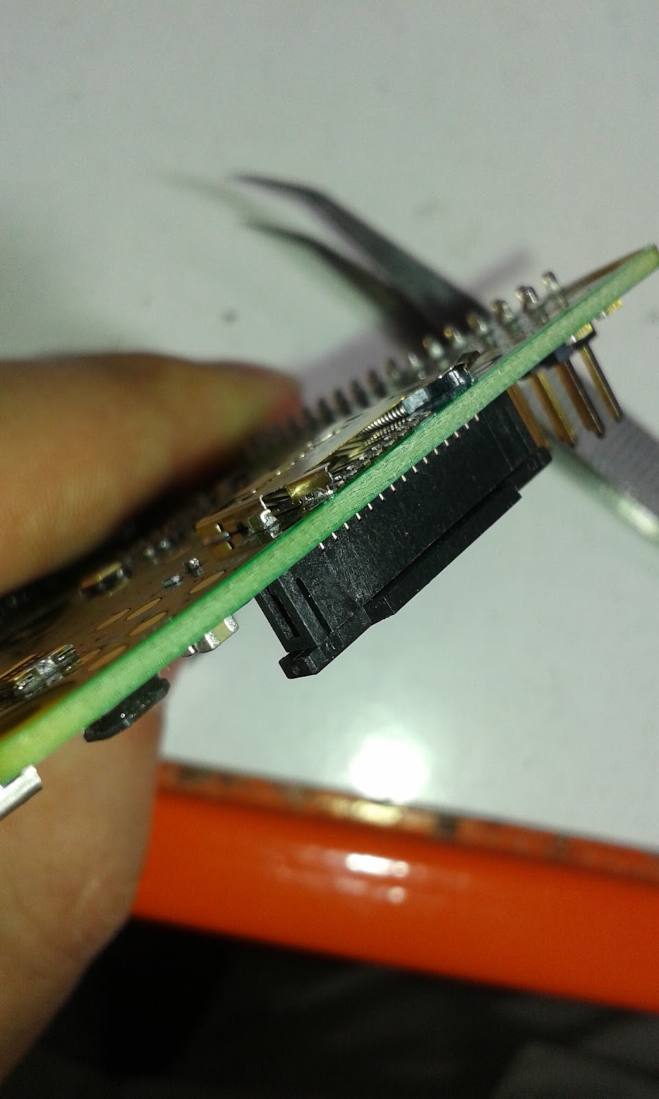
Use some good sharp tweezers to lift the the tab of metal housing at the edge of the Raspberry Pi.


Once that is lifted then used the tweezers to hook out the the plastic catch and spring.


Then it is just a case of folding the tab back down again and squeezing the housing slightly so that it applies some pressure on the SD Card when it is inserted.


After that it should be a case of sliding in the SD card and powering up if you have done this right the Pi should boot.


I normally add a little tape over then in SD card just to make sure it don't knock it out.

Hope this helps some people out as mentioned at the beginning you are essential breaking the socket to fix it.