CHUSBIE552

Sunday, 5 July 2015

What makes a DHT11 temperature humidity sensor Tick

A DHT11 is very low cost and well supported temperature and relative humidity I've had a few of these for a while and always wondered how they work. I think its time for a TEARDOWN.


There are a lot manufactures for the DHT11 this one is made my AOSONG. It can run between between 3 and 5 volts and uses a simple one wire protocol to communicate with other devices. For more details on the sensor itself check out the datasheet.


The casing is in two parts so to get inside it is just a matter of getting a sharp knife and splitting the case apart.


Inside the case is a small PCB with a SOIC 14 packaged IC unfortunately the part number has been removed so there is really no way to tell if this is a custom part or a specially programmed MCU. along the edge of the IC are couple of  ceramic capacitors for decoupling and noise suppression, and some other misc passive components. The green resistor I can assume is a precision resistor for the humility sensor (explained in more detail later).  


On the other side the sensor hardware itself. This consists of a PCB with interlaced traces that creates capacitance this with change based on the amount of moisture present in the air around it.  


HOW DOES IT WORK

The interlaced +ive and -ive traces allow a small amount of charge to be stored in each of the traces allowing the circuit to charge up a little, this is called capacitance and this is effected by the material separating the +ive and -ive which is mostly air and its airs permittivity one of the factors for calculating capacitance is affected by temperature and humidity
So the chip uses the precision resistor I mentioned earlier and measures the discharge time through that resistor to calculate the capacitance, and then uses that figure used with the internal temperature sensor inside the main IC to calculate the relative humidity.
    

Tuesday, 23 June 2015

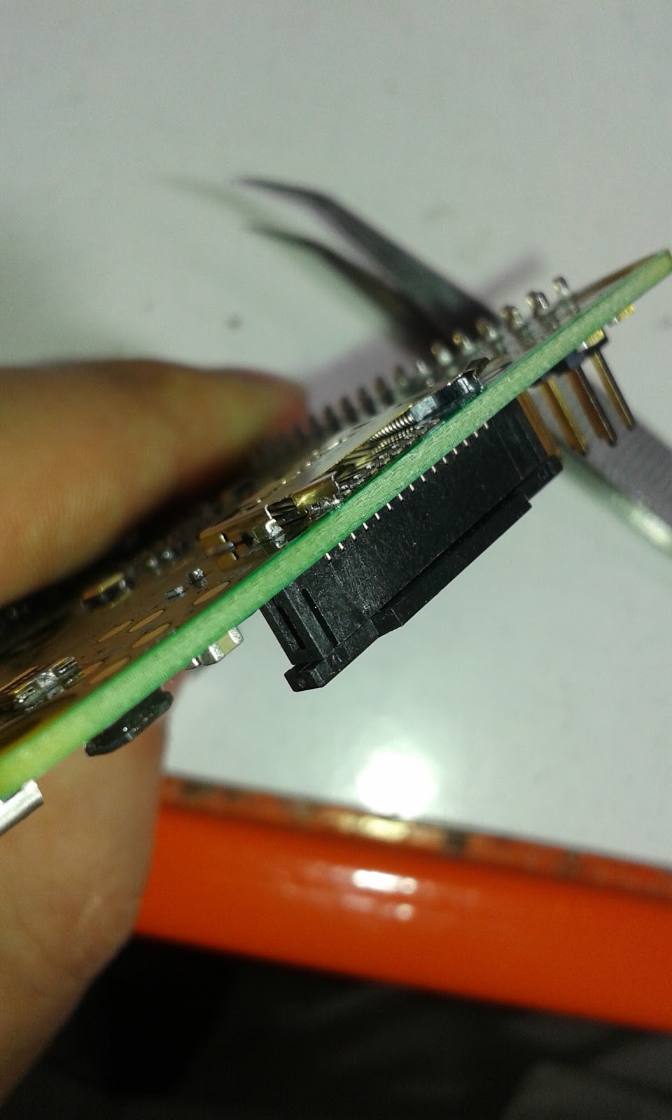
Dirty Hack: repairing (Breaking it better) a raspberry A+,B+ or 2 microSD card Socket

This is just a quick and dirty hack that i have had to perform once in a while. Sometimes and I have to say this problem is quite rare the catch that holds the microSD card in the socket fails and it is impossible to get the card to stay in place.


I have had this problem passed over my desk a few times I have a little fix/break for this that works.

WARNING: ONLY TRY THIS AFTER EXHAUSTING ALL OTHER POSSIBILITIES OF REPLACEMENT OR REPAIR AS YOU WILL BE DAMAGING THE MIRCO SD CARD SOCKET FOR THIS TO WORK. THERE IS NO GUARANTEE THIS WILL NOT RENDER YOUR RASPBERRY PI MORE BROKEN THAN IT ALREADY WAS :)  I TAKE NO RESPONSIBILITY FOR BROKEN RASPBERRY PIs

So basically we are going to remove the catch and spring that retains and ejects the SD card. Hopefully without damaging the contacts.


Use some good sharp tweezers to lift the the tab of metal housing at the edge of the Raspberry Pi.


Once that is lifted then used the tweezers to hook out the the plastic catch and spring.


Then it is just a case of folding the tab back down again and squeezing the housing slightly so that it applies some pressure on the SD Card when it is inserted.


After that it should be a case of sliding in the SD card and powering up if you have done this right the Pi should boot.


I normally add a little tape over then in SD card just to make sure it don't knock it out.

Hope this helps some people out as mentioned at the beginning you are essential breaking the socket to fix it.

Thursday, 18 June 2015

Ryan Tech Debug Clip (Assembly)

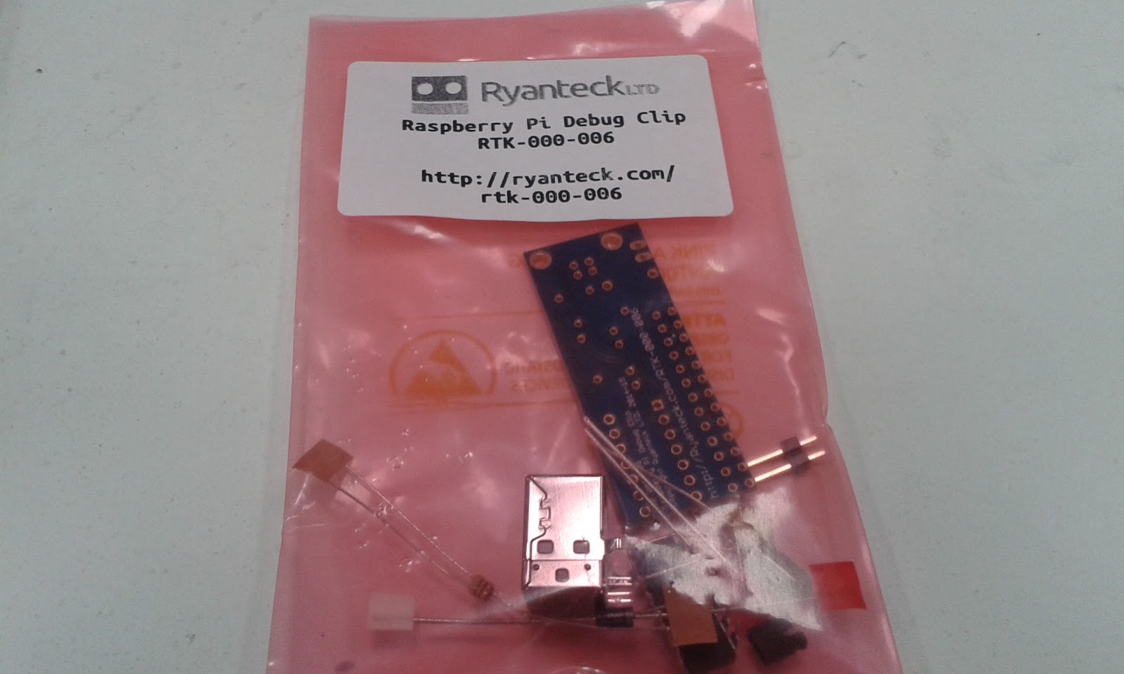
I was passed a Ryan Tech Debug Clip, a little board that allows you to connect to a Raspberry Pi via USB and the UART connections on it's GPIO this was due a good friend of mine Gadgetoid  had 2  from backing the Kickstarter.

I got interested in this watching Gadgetiod solder up the realising that it wasn't just another FTDI FT232R (being honest no happy with them after the hole bricking your device scandal, long story) or a Prolific PL-2303. It was using something unexpected Microchip MCP2221.

This little chip is not only a basic USB to UART bridge it can also bridge to GPIO, I2C and a tonne of other functionality. This really peaked my interest but that will be for a later blog post. This post i'm looking the assembly and what comes in the kit.

The Debug Clip clip comes in kit form requiring soldering together don't be too put off by this as all the joints are well spaced and it has plenty of guidance on the PCB's silkscreen.


In the kit is:

  • PCB 
  • A USB Type B socket 
  • A two pin header with jumper 
  • A green and a red LED
  • A diode 
  • Two Resistors of the same value 
  • A fuse
  • And the MCP2221 IC itself

One thing to note there was ESD foam protection on the legs of the IC. The foam would offer some electrical protection but the main reason would be to prevent the legs from being damaged in shipping.


The kit feels well thought through, the silkscreen on the PCB makes assembly even easier. There is a clear assembly guide provided by Ryan Tech but the Silk was so clear I didn't even need to look at it.

Assembling 


There are only a few things to make sure the orientation is correct the IC, the diode and the two LEDs.


I started assembling mine with the diode and resistors the have the lowest height to the board and folded the legs outwards before soldering. Then solder and trim with some side cutters.


The IC itself was next in height order it always worth making sure that the notch on the IC matches the pattern on the silkscreen.


Next I decided the the USB socket would be the best as it would create a flat surface to rest on this help with supporting the header when soldering that in, making sure to solder one contact on the header first and then reheat the join and push the part flush with the PCB (Mind you fingers it could get hot) 

Then it was onto the LEDs I chose the green one for RX and the red for TX. The positions are well marked with a little + for the positive side, which is the longer of the two LED leads.


The last component I assembled was the fuse then all was done for the moment.


All ready to plug into your Raspberry Pi and PC's USB port.

Installing drivers 

The Debug Clip's driver are not available in windows update at the moment but can be easily downloaded from the Microchip MCP2221 Product page.


If the device is working correctly it will appear in your device manager as other devices -> MCP2221 USB-I2C/UART Combo. Please note that the Clip will not work unless placed on a the Raspberry Pi's GPIO header, as it uses the Pi's 3.3v regulator to make sure the UART output is 3.3v so it doesn't damage the Pi. Also make sure that the Pi is on. 

So now go ahead and download the appropriate driver for you. I'm running a Windows 8.1 laptop so mine is the Windows Driver & Installer. 

Once downloaded open the archive and extract the files.


Navigate through the Driver Installation Tool and relevant 32 or 64 bit version and right click on the .inf file and select install from the menu. ( for me the installation tool didn't work )


 Then the device should appear in your device manager. This would be a really good point to  take note of which COM port the Clip appears on. (In my case it is assigned to COM10).

Using the Debug Clip

You are going to need a remote terminal program if you don't have one already, I use Putty and would recommend it for most users. I can be downloaded form here.

Once you have Putty running click on the Serial radio button and enter your COM number that you noted earlier and set the speed to 115200.


After clicking open a terminal window should appear and you will be asked to login with the normal user name a password.


Then you can just use it as though you are on the Raspberry Pi's command line.

I like the Debug Clip and it is nice to have the blinking green and red LEDs as the data is going back and fourth. It makes a good alternative to the FTDI or Prolific based boards that are out there. the assembly we very straight forward with no real issues. I give it 4 sparks, 3 for the device and and bonus for hack-ability. 


Then next Post do will be about modding and hacking the Debug Clip.


Monday, 15 June 2015

Simulating Keyboard Input in Python (Linux)

This is a big question that has very little good answers too it as I found out. Sorry if this is a little dry but this need to be shared.

NOTE: This is orientated towards Linux Python 2.6, the Windows Python solution is different.

How to I get Python to simulate keyboard key presses and releases?  For me this came up while trying to make a custom capacitive touch  controller with a on a Raspberry Pi for use with MAME or Minecraft Pi edition.

For this we going to use a Python Module called Uinput. This module can simulate keyboard, mouse or custom device. It can also migrate happily between programs in the desktop environment as well as the command line.

All of the following need to be completed on the command prompt or in a terminal window so if you are on the desktop go ahead and open your terminal program.


Prerequisites

There are a couple of extra development libraries that need  to be installed, before installing the python module otherwise Uinput will refuse to compile and install.

First of all it is always worthwhile making sure your apt repositories are up to date it is a good rule to do this before installing any new software, so to do this you need to
sudo apt-get update 
Then the development libraries that you need to install are libxtst-dev

sudo apt-get install libxtst-dev


Installing the module


Make sure that you have the python pip installer installed this will make it easier to build an install on your Linux system.
sudo apt-get install  python-pip
Then to install the module using the python pip installer.

sudo pip install python-uinput
If all the prerequisites are satisfied this will download compile and install the python module. :)

The module requires Uinput kernel module to be running this can easily be done with
sudo modprobe uinput
This will load the module this time round. I you want it to load every time you reboot your system then it will need to be added to the /etc/modules file. To edit the file from your command line.

sudo nano /etc/modules
Add an extra time to the line to the file with.
uinput
Then.
Ctrl + x
This will save and exit just hit  Y to confirm overwriting the file.


Using the module


So now that is all complete its only a case of writing some code.
import uinput
device =  uinput.Device((uinput.KEY_W,uinput.KEY_S))
import time
while 1:
        device.emit(uinput.KEY_W,1)
        time.sleep(0.5)
        device.emit(uinput.KEY_W,0)
        time.sleep(0.5)

This is a  little sketch to setup a two button device I'm just using this as an example but any device can be made with any number of keys so lets have a look at the code.

Lets have a look at what the code is doing.
import uinput 
This imports the required module into your python sketch.
 device =  uinput.Device((uinput.KEY_W,uinput.KEY_S))
This line creates a uinput device with two keys W and S all the letter keys emit as there lower case version unless it is modified with a shift.

import time
imports the time module for handling delays
while 1:
Repeat forever
        device.emit(uinput.KEY_W,1)
Keydown w key
        time.sleep(0.5)
wait 0.5 seconds
        device.emit(uinput.KEY_W,0)
Keyup w key
        time.sleep(0.5)
  
 This module could be used for making custom combos for games in MAME like street fighter or just allow automated control of some command line tasks. I am currently using it to make a custom game controller on with a Raspberry Pi's  GPIO connection.

Hope this helps out a few people as I found it tricky to get up and running in the first place hopefully I have covered that so people don't have the same difficulty.


Sunday, 14 June 2015

Fun with the Silicon Labs BIOMETRIC-EXP-EVB development board

This week I've been having a good look at the the BOIMETRIC-EXP-EVB dev board from Silicon Labs a Fab-less chip manufacturer based in Austin Texas.

The board is designed as an expansion board for their EMF32 Wonder GEKO development system. The board contains a SI1146 Ambient, IR , UV and 2D Gesture sensor, SI7013 Temperature and humidity and a TS3310 step up DC to DC coveter. The dev board also contains a Microchip 24AA024 eeprom that I believe it communicates with other Silicon Labs contains specific info about the board. It also has a green and red LED for good measure. This development board is around $29.00 at the moment so if you fancy toying with a selection of sensors then I recommend it.  

 This week I've been specificity trying out the  SI1146. This chip has the ability to  measure ambient light level, Infra red level and  measure UV index which is a standardised measurement of UV light level normally used in calculating sun burn time. The chip is also can sense 2D gestures using 2 external infra red LEDs its internal LED constant current driver and taking independent reading of refection from each of the LEDs with can then be used to calculate distance on 2 axis (distance from chip and north/south or east/west depending on the LED location)

Wiring up 

Just to note the development board is runs both power and logic at 3v3 so if your are using a 5v platform like and Arduino Uno you will require a I2C compatible logic level shifter for that data lines or there is a risk of damaging the dev board.

All the devices on the board communicates with a two wire serial protocol called I2C. This is a bus based protocol that requires devices on the bus to have individual 7 bit addresses. To use these I2C devices SDA ( serial data ), SCL (serial  clock ) and GND ( ground ) need to be connected.

 There is a little bit of a got-ya with wiring up this board  in the datasheet states that the the Si1146 SDA is connected to pin 16 and SCL is connected to pin 17 this is true for the JP3 header this is the one on the left side of the board, but on the right side the JP4 header it is connected to pin 15.  The INT pin is used for interrupt driven reading of the sensor when it when a sensors readings are ready this pin will change.

For my tests I'm using a Raspberry Pi B+  and coding in python using the SMBus module which runs the Raspberry Pi's I2C bus.

The pin numbers start at the bottom or south of the board and go across the header starting from the bottom row hopefully this picture makes more sense.


so hook up:
Raspi                                              Biometeric board
Pin 1                     3.3v                    Pin 2
Pin 3                     SDA                   Pin 16  
          Pin 5                     SCL                    Pin 17 on JP3 or Pin 15 on JP4
Pin 6                     GND                   Pin 1

Software 

I have spent a few hours getting this to run in Python and at this moment still working on the code to make it into a python module for the Si114x range possibly for a future development. My work so far is available on github Here.

The moment it is just a single program that runs the Si1146 and outputs its data on screen. 

So just type:

git clone https://github.com/rabid-inventor/SI1146-software.git
Then
cd SI1146-software/RaspberryPi/Python/
and to run the python script
sudo python si1146.py

This will output UV index , Proximity sensor and visible light level.

currently having a lot of fun with this sensor and will keep updating especially when I get as far as using the sensor to measure pulse and 2D gestures. At a later stage I will be revisiting the Si7013 temperature humidity sensor an see if I can finally get it running with a Raspberry Pi. 


Wednesday, 27 May 2015

Pi Supply Gert VGA666 Software Setup and Test


This is how to Set up the Gert VGA666 for Pi Supply I have a previous post on assembling the components if you haven't already done so please check it out here.

Installing and Configuring software 


Be aware that you are changing the where the Pi is going to output it video if you have the option I would recommend setting up over an SSH connection.

Firstly you'll need to download the required software to run the Gert VGA 666. Make sure your Pi has an internet connection.
git clone https://github.com/fenlogic/vga66.git


Then you will need to copy the driver file into /boot/ and rename it.
cd vga666/setup/
sudo cp dt-blob-dpi.bin /boot/
sudo mv /boot/dt-blob-dpi.bin /boot/dt-blob.bin

Now the final step is to add it to your raspberry pi configuration.

So to open the configuration file.
sudo nano /boot/config.txt
The you'll need to add.
 enable_dpi_lcd=1
display_default_lcd=1
This will enable the VGA output. Then you can set the output resolutions by adding
dpi_group=2
dpi_mode=82
 For 1080p @60Hz or.
dpi_group=2
dpi_mode=86
 For 1366 x 768 @60Hz


These are the two screen modes I have tried myself please now the resolution values are the same as setting the resolution for the HDMI output, a full list can be found here.

Problems you may run into 

The first time that I tried this the VGA work for about 10 seconds of boot time the the text turned yellow and then vanished dropping my screen into power saving.


I was using a Rasbian image that had some of the GPIO setup for various tasks so it was 'grabbing' some of the GPIO for other tasks this was fixed with a fresh burn of Raspbian.


In conclusion 

This is great add-on to the Raspberry Pi and the documentation makes for interesting reading as it goes into an explanation of how it generates and analogue signal from the GPIO header, and makes for great learning and soldering practice.

This is in no way the perfect solution for VGA output on the Raspberry as it will have the occasional slight shimmer on the display and it uses huge chuck of you GPIO to drive it. So if your you are looking for a VGA output from your Raspberry Pi I'd recommend a good HDMI to VGA adapter.

So I award this 3 of 5 Sparks it was fun to assemble the documentation could be a little clearer but as a learning exercise it's fantastic.

Sunday, 24 May 2015

Pi Supply Gert VGA666 Assembly

So i have had this rocking around for some time now and I though it was high time that i gave it a test run.

This is the Gert VGA666 from Pi Supply. Designed a by Gert Van Loo of Raspberry Pi fame and ran as a successful kickstarter campaign back in October 2014 ( which is where mine has come from ).

The Gert VGA666 is a clever breakout board for the Raspberry Pi that allows it to use the GPIO header to generate a VGA signal.  This done with only 20 Resistors to mimic an analog signal  the VGA monitor use the obvious downside to this is that you use up a lot of the GPIO pins.

 Assembly       

On the Pi Supply product Page there is a link to a Github Repository that contains the instructions, some of the details on how it works and the required files to make the Pi work with it .


This is the what comes in the Kit:
  • PCB 
  • 20 Resistors 
  • VGA socket 
  • extended GPIO Connector 
  • 2 Stickers and a Business card directing you towards the Pi Supply Website 
 This first thing I recommend doing is layout the parts and use a multimeter to check and label the tapes of resistors with all their values on the blue cased film resistor I find the colours hard to distinguish so i usually go straight for the multimeter as better choice than tying to remember my resistor band colours.


Labeling just helps when you come to the placing the parts. there should be:

  • 2 x 120 ohm
  • 3 x 500 ohm
  • 3 x 1K ohm
  • 3 x 2K ohm 
  • 3 x 4K ohm
  • 3x  8K ohm 
  • 3 x 16K ohm 

I find the colour key in the instruction a little hard to follow so here is a Bill of Materials for the Resistors.
 Label            Resistance (ohms)
R2 -          500
R4 -          1000
R6 -          2000
R8 -          4000
R10 -        8000
R12 -        16000
R14 -        500
R16 -        1000
R18 -        2000
R20 -        4000
R22 -        8000
R24 -        16000
R26 -         500
R28 -        1000
R30 -        2000
R32 -        4000
R34 -        8000
R36 -        16000
R38 -          120
R40 -          120

Then it is just a case of placing all the resistors in their correct locations and fold the leads outward for me I like to place all the resistors first as this lest me see if I have any location wrong before soldering.


The back of the PCB becomes a bit of a 'Rats Nest' of resistor leads but there is plenty of space to solder them form the topside.


After soldering use a sideways cutter to trim all the leads if and if there are any joins looking a little low on solder apply more (best to do this as a better solder joint will give a more stable signal).


 now make sure the PCB is the correct way up for the next bit the instructions say 'The Connectors are at the same side as the surface mount resistors'

Then it is just a case of soldering first the GPIO connectors soldering one corner pin first to make sure that it is flush to the board then solder the rest of the pins you can insert the VGA connector if it makes the PCB a bit more stable to solder for you.

Then solder up the VGA connector.

ALL Assembled!

I will continue the software setup and testing in another post. Click Here